Encoder communication circuit

a communication circuit and encoder technology, applied in the field of encoder communication circuits, can solve the problems of recurrence of abnormalities, time is required for identification of fault locations, and further time is taken for restoration, so as to shorten the time for restoration of the apparatus

Active Publication Date: 2014-09-02
FANUC LTD
View PDF25 Cites 3 Cited by
  • Summary
  • Abstract
  • Description
  • Claims
  • Application Information

AI Technical Summary

Benefits of technology

[0009]The present invention was made in consideration of the above problems and has as its object the provision of an encoder communication circuit able to identify an abnormal location and shorten the time for restoration from the abnormal state when a communication abnormality occurs.
[0014]According to the present invention, at the time of an abnormality in communication of a system or an apparatus using an encoder, it is possible to identify the fault location and possible to shorten the time for restoration of the apparatus. Further, if sending data indicating that the encoder is not in the initial state, the control apparatus will not output an alarm invalidating the storage of the origin position of the machine. Therefore, when it is judged there is trouble other than at the encoder and continuing to use the original encoder, the work of resetting the origin becomes unnecessary. Further, when outputting alarm data for preventing machine operation, it is possible to prevent the machine from mistakenly being placed in the operating state and perform the work for confirming the fault location safely.

Problems solved by technology

However, if the communication circuit of the encoder breaks down, the communication cable breaks, the communication circuit of the control apparatus breaks down, etc., the control apparatus detects the communication abnormality and displays an alarm, but the communication is cut, so time is required for identification of the fault location.
Further, if the fault location is mistakenly identified, the abnormality will reoccur even after the parts are replaced and further time will be taken for restoration of the apparatus.
However, with this method, since the other encoder was in the initial state, an initial state alarm showing that the absolute position was not established was sent to the control apparatus.
When the control apparatus recognized that the encoder was in the initial state, it ended up invalidating the origin information stored for displaying the absolute position of the original encoder.
For example, sometimes a break in the communication cable is the cause.
However, if reconnecting the original encoder to the control apparatus, since the origin information is invalidated, the origin has to be reset.
This operation for setting the origin requires the reproduction of the predetermined origin position of the table or machine, so depending on the configuration of the machine, complicated, precision work using reference jigs or dial gauges or other measuring devices becomes necessary.
Further, the other replacement encoder for finding the cause of an abnormality would be expensive.
Use for finding the cause of an abnormality would be uneconomical.
Further, if connecting another encoder, the machine might mistakenly be placed in the operating state, so the work would be accompanied with danger.

Method used


Image

  • Encoder communication circuit
  • Encoder communication circuit
  • Encoder communication circuit

Examples


Embodiment Construction

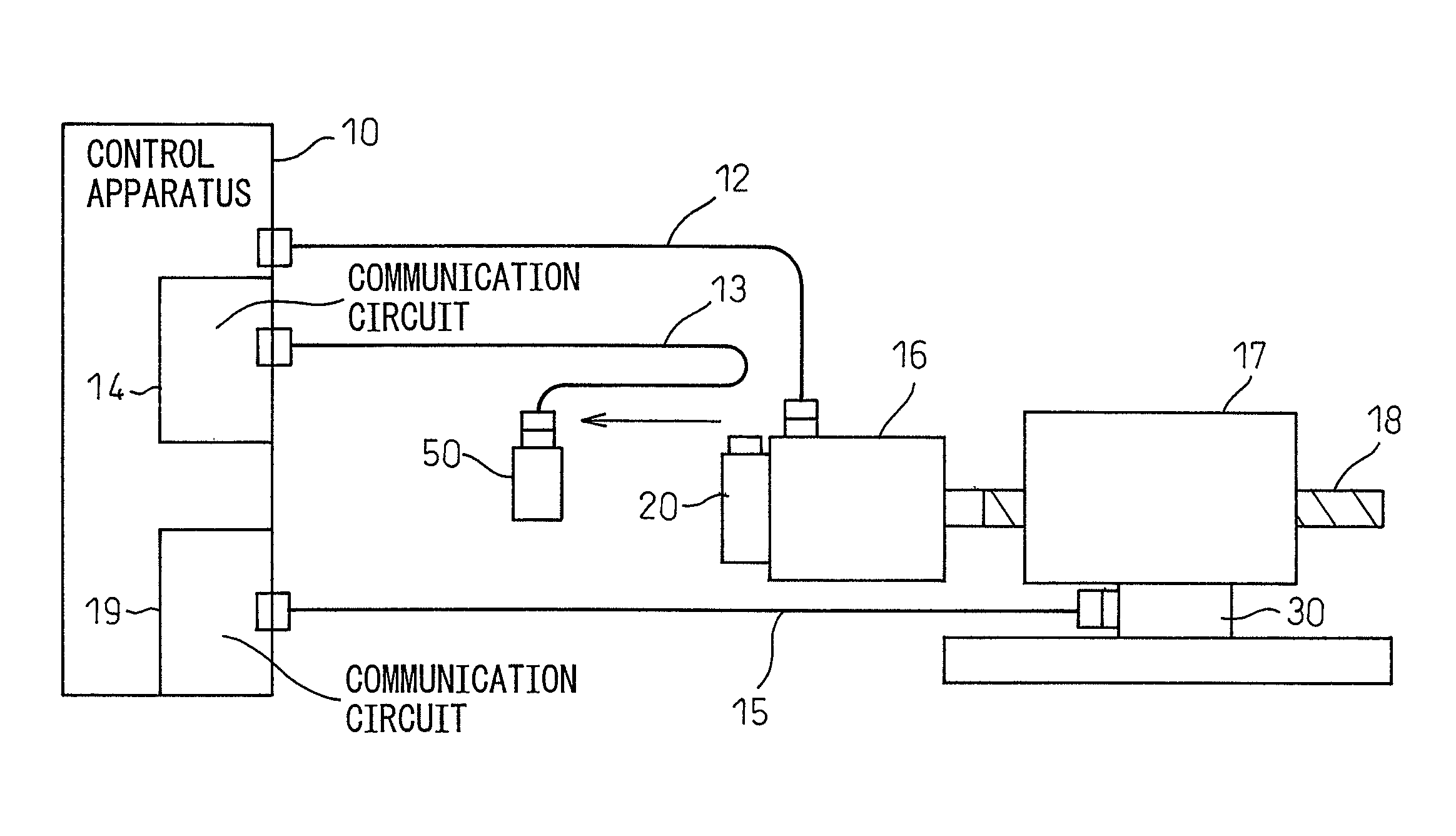
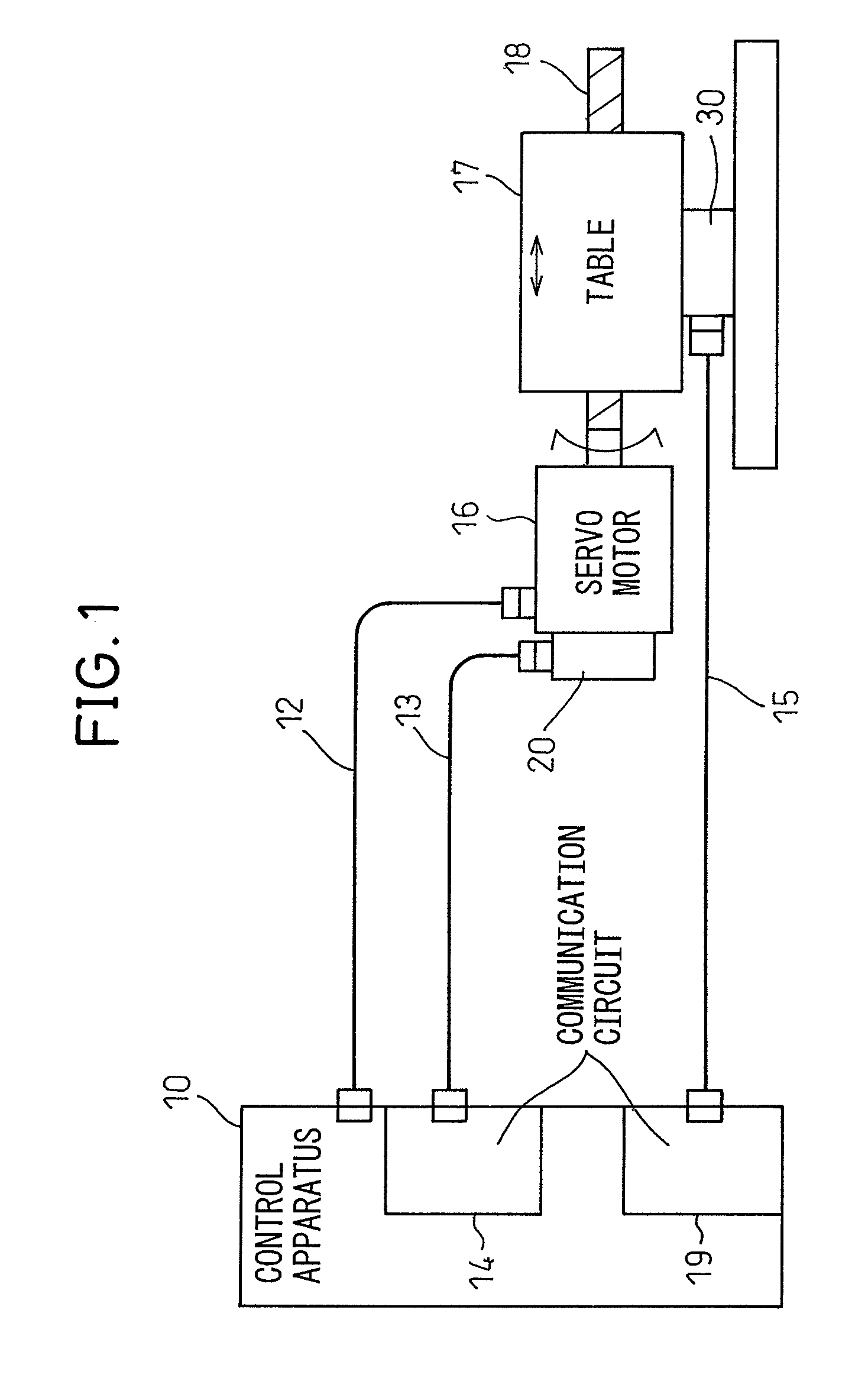
[0025]Below, embodiments of the present invention will be explained while referring to the drawings. Before that, however, referring to FIG. 1, a general work apparatus of an example to which the present invention is applied will be explained. The work apparatus uses information from encoders 20, 30 to feedback control a servo motor 16 to make a table 17 move.

[0026]A control apparatus 10 is connected with the servo motor 16 to be controlled through a power line 12. Further, the control apparatus 10 is connected by communication circuits 14, 19 of the control apparatus 10 and first and second signal lines 13, 15 to a first encoder 20 built in the servo motor 16 and a second encoder 30 for detecting the position of the table 17.

[0027]The control apparatus 10 uses a communication circuit 14 to communicate with the first encoder 20 through the first communication cable 13. The encoder 20 detects the position or speed of a shaft of the servo motor 16 and sends the detection signal to the...


PUM


Abstract

When a communication abnormality occurs between an encoder and communication circuit apparatus in a work apparatus feeding back data output from encoders for control by a control apparatus, an encoder communication circuit is used in place of the encoder to identify the location of occurrence of the abnormality. The encoder communication circuit outputs encoder data comprised position or speed data and alarm data to said control apparatus when connected to the control apparatus through a communication cable.

Description

RELATED APPLICATIONS[0001]The present application is based on, and claims priority from, Japanese Application Number 2006-267296, filed Sep. 29, 2006, the disclosure of which is hereby incorporated by reference herein in its entirety.TECHNICAL FIELD[0002]The present invention relates to an encoder communication circuit used in place of an encoder for identifying an abnormal location when an abnormality occurs in an apparatus using an encoder.BACKGROUND ART[0003]In recent years, encoders obtaining position or speed information as electrical signals have become higher in resolution and have become able to handle higher speed rotations. The method of outputting signals from encoders is also changing from the conventional A / B phase output method to the method of transferring data by serial communication not governed by the resolution or rotational speed. Data transferred by serial communication includes not only position information, but also alarm information indicating an abnormality ...

Claims


Application Information

Patent Timeline
Patent Type & Authority Patents(United States)
IPC IPC(8): G08B19/00G08C19/12G08B21/00G01D5/244H02P29/00
CPCG01D5/24457
Inventor TANIGUCHI, MITSUYUKIKIKUCHI, HIROFUMI
Owner FANUC LTD
Why Eureka
Try Eureka