Protective wall

a technology for protecting walls and walls, applied in the field of protective walls, can solve the problems of not being able to use protective walls, and achieve the effects of increasing the stability and stiffness of the two holding plates, increasing the load, and increasing the stability of the holding fixtures

Active Publication Date: 2014-09-09
FEIGL BERNHARD
View PDF15 Cites 0 Cited by
  • Summary
  • Abstract
  • Description
  • Claims
  • Application Information

AI Technical Summary

Benefits of technology

[0010]It is, therefore, a task of the present invention to provide a protective wall of the aforementioned kind based on the balustrade of prior art which is reliably supported on a floor and (even given considerable wind loadings or other external loading situations), and can be installed and removed quickly and easily.
[0012]The U-section rail, together with the panel inserted therein, can be pushed onto two holding plates running in parallel with one another and attached to a holding fixture, because a U-shaped and outwardly projecting holding pocket is formed onto each of the two free ends of a leg. The holding fixture, in turn, is connected to the floor in a releasable connection which is firm when it is attached, with the effect that the holding fixture, and thereby the holding plates, reliably support the U-section rail and the panel inserted in it on the floor. The holding fixture can be attached to the floor quickly and easily and / or the U-section rail can be disconnected from the holding fixture, which means that the installation or removal of the panels can be performed quickly by users who do not require any specialist training or knowledge in order to do this.
[0014]In order to provide additional support for the holding fixture on the floor, a stabilisation plate may be inserted between the holding fixture and the floor, in which case the stabilisation plate projects beyond the outer contour of the holding fixture with the effect that objects, such as flower tubs and concrete slabs, can be placed on the stabilisation plate in order to increase the load.
[0015]Stabilisation of the holding fixture is increased in an advantageous manner in particular in that a web is provided between the upper holding plate inserted in the holding pocket of the U-section rail and the legs of the holding fixture running parallel to the floor, with the effect that the holding fixture together with the holding plate have a triangular cross-sectional contour. In case of particularly high loadings, such as between housings in which there can be flows of air from both sides, the web is also formed onto the second holding plate so that the holding plates, together with the holding fixture, form a triangular cross-sectional contour. As a result, the holding plates are additionally supported on each of their outer sides by means of the web on the holding fixture.
[0016]In order to increase the stability and the stiffness of the two holding plates, as well as to lock adjacent U-section rails, plate-shaped connecting elements are provided which can be pushed in sideways between two holding lugs arranged flush with one another on each U-section rail. As a result, two U-section rails can be assembled in alignment with one another, or for forming a corner, by means of the connecting elements.

Problems solved by technology

Designs of this kind have proven themselves in practice in balustrades as protection against falling, although they cannot be used for protective walls that are to be erected on a floor, because such balustrades require unobstructed access to an end face of the fixed floor, or wall, in order to support the U-section rail reliably on the floor by means of the holding fixture.

Method used


Image

  • Protective wall
  • Protective wall
  • Protective wall

Examples


Embodiment Construction

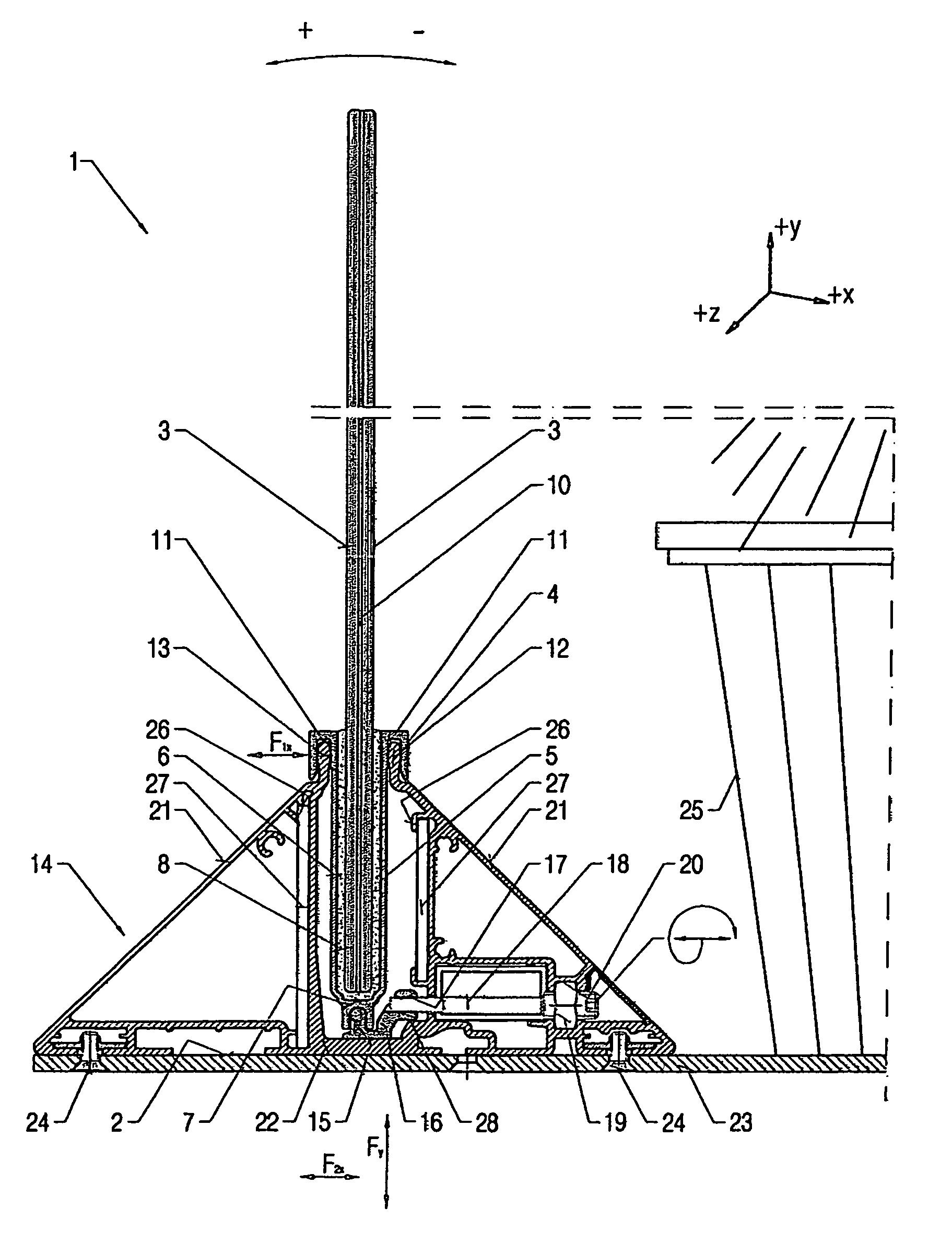
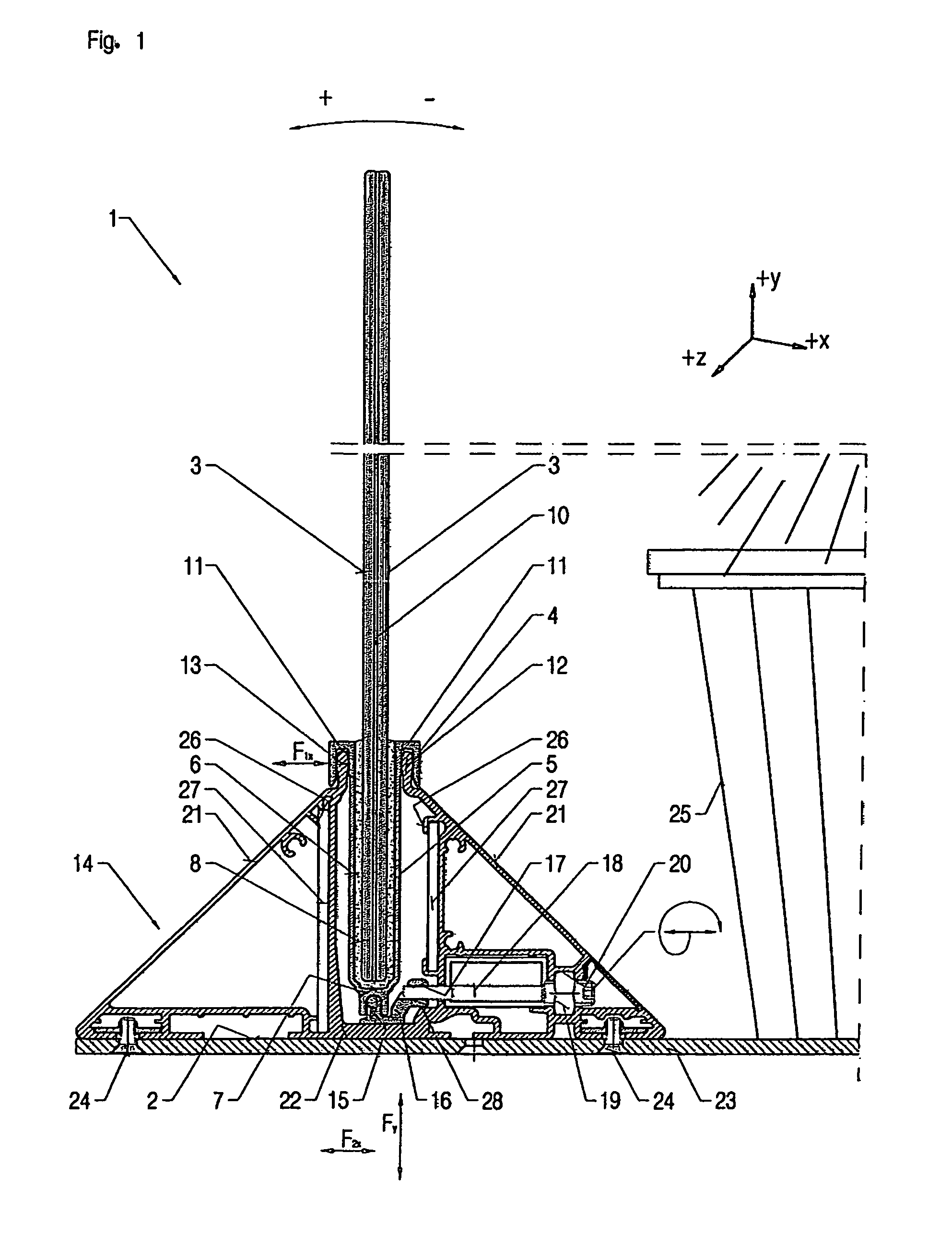
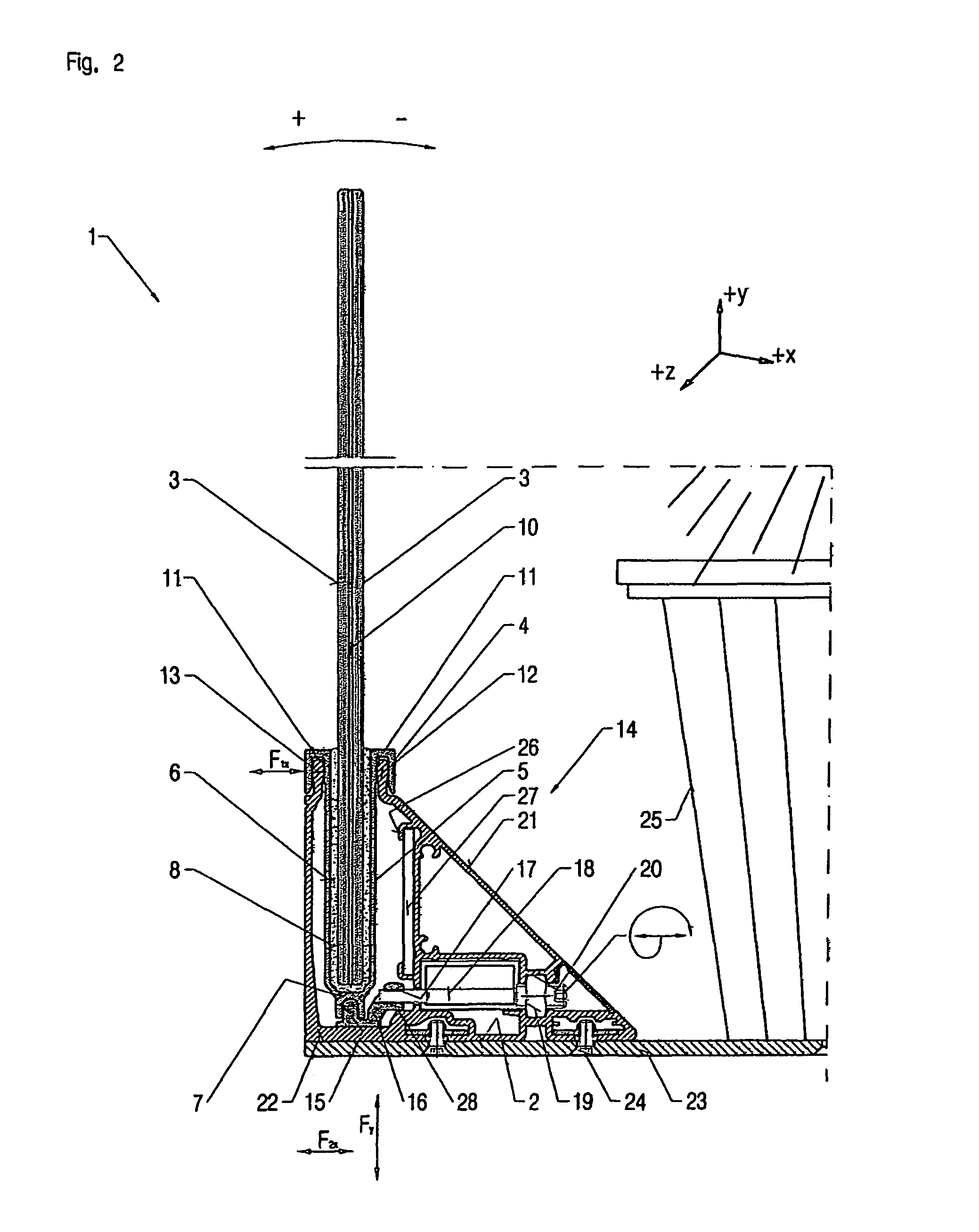
[0021]In FIG. 1 there is shown a protective wall 1 by means of which drafts are prevented in the area of terraces, in order to protect people against drafts, for example. The protective wall 1 is mounted on a floor 2 by means of a holding fixture 14 explained in more detail below, with the effect that the protective wall 1 can withstand loadings caused by the effect of wind force and does not fall over as a result. Furthermore, the protective wall 1 should be able to be installed in and removed from the holding fixture 14 as quickly and easily as possible, in order to allow the wall 1 to be protected from frost and other damage during winter months, by keeping the wall in storage rooms.

[0022]The protective wall 1 comprises a U-section rail 4 in which, in the illustrated embodiments, two panels 3 are firmly installed at a factory by means of a layer of glue 8. The two panels 3 are secured together by a foil 10 to form a pane of safety glass. This means the panels 3 and the U-section ...


PUM


Abstract

A protective wall releasably connectable to a floor, the wall comprising panels, a U-section rail with legs extending in parallel, and a web gripping the panels and locked thereon. A U-shaped holding pocket is disposed on free ends of the legs of the rail and is disposed such that a holding plate is insertable into each holding pocket, the holding plates being attached to a holding fixture fixed onto a floor, a holding groove is provided on an outside of the web, and a locking body is disposed in the holding groove, such that the locking body is supported on the holding fixture and is mounted such that it is moveable in a horizontal direction relative to the holding fixture.

Description

BACKGROUND OF THE INVENTION[0001]1. Field of the Invention[0002]The invention relates to a protective wall releasably connectable to a floor.[0003]2. Description of the Prior Art[0004]A holding fixture for a glass panel of a balustrade is disclosed in EP 2194207 A1. The glass panel is inserted in a U-section and glued therein, with the effect that the glass panel and the U-section are firmly connected to one another at a factory, in order to be subsequently connected to a building floor by means of a holding fixture attached to the floor.[0005]The balustrade serves in particular as a means of preventing falling from a balcony, stairs, or an intermediate floor in a building, with the effect that legally specified safety standards regarding the stability of the balustrade are complied with and reliable protection against falling is achieved in case of high lateral loadings, and protection against falling is reliably provided on an intermediate floor or balcony, even after a certain se...

Claims


Application Information

Patent Timeline
Patent Type & Authority Patents(United States)
IPC IPC(8): E04H1/00E04F11/18
CPCE04F11/1851E04F11/1812E04F11/1853
Inventor FEIGL, BERNHARD
Owner FEIGL BERNHARD
Why Eureka
Try Eureka