Heat exchanger

a technology of heat exchanger and heat exchanger body, which is applied in the direction of machines/engines, lighting and heating apparatus, laminated elements, etc., can solve the problems of limited operating life of evaporator heat exchanger, high temperature changes in evaporator heat exchanger, and high thermal load on evaporator heat exchanger. , to achieve the effect of high thermal

Inactive Publication Date: 2014-09-09
BEHR GMBH & CO KG
View PDF23 Cites 2 Cited by
  • Summary
  • Abstract
  • Description
  • Claims
  • Application Information

AI Technical Summary

Benefits of technology

[0010]In an embodiment, the object is attained with a heat exchanger, comprising plate pairs stacked one above the other, whereby a first flow chamber is formed between the two plates of a plate pair for conducting a first fluid therethrough, a second flow chamber for conducting a second fluid therethrough, whereby the second flow chamber is formed between two adjacent plate pairs, an inlet aperture for introducing the first fluid, an outlet aperture for discharging the first fluid, whereby the plates have at least one expansion opening, in particular at least one expansion slit, for reducing stress in the plates.
[0011]In an embodiment, the plates, for example, one or both plates of a plate pair, are provided with at least one expansion opening. The at least one expansion opening has any desired cross section; for example, it is circular, rectangular, square, or ellipsoidal. In particular, the expansion opening is formed slit-shaped as an expansion slit. Owing to the expansion openings in the plates, stress in the plates, resulting from the high thermal loads of the heat exchanger, can be greatly reduced in an advantageous manner, so that only very low shear stress occurs between the plates and the spacers of the heat exchanger. Stress between the plates can be relieved at the expansion openings, because there is a space for accommodating thermally induced changes in plate size at the expansion openings.
[0014]The at least one expansion opening can be formed in the plates between the inlet through hole and the outlet through hole. The spacers are arranged between the inlet through hole and the outlet through hole in each case between the plate pairs. Thermally induced changes in size or changes in the shape of the plates are especially critical here, because with a change in size or deformation of the plates between the spacers high shear stress must be absorbed to a different extent on the spacers. If, for example, a plate pair is heated much more greatly than a plate pair below it, the more greatly heated plate pair expands much more greatly, so that as a result different changes in the size of the plate pairs occur at the spacers and thereby high shear stress must be absorbed on the spacers. Because of the formation of the at least one expansion opening between the inlet through hole and the outlet through hole, such changes in the shape of plates can be accommodated, so that the arising shear stress on the spacers, i.e., between the plates and the spacers, can be substantially reduced thereby.
[0025]In another embodiment, the waste heat from the main exhaust gas flow of the internal combustion engine and / or the waste heat from the EGR and / or the waste heat from the compressed charge air and / or the heat from a coolant of the internal combustion engine can be utilized by the system as a component of the internal combustion engine. Thus, the waste heat from the internal combustion engine is converted to mechanical energy by the system and thereby the efficiency of the internal combustion engine is increased in an advantageous manner.

Problems solved by technology

In this regard, high temperature changes occur in the evaporator heat exchanger during operation of a system for utilizing the waste heat of an internal combustion engine.
As a result, the evaporator heat exchanger is exposed to high thermal loads.
Such high shear stress leads to leaking and thereby to a limited operating life of the evaporator heat exchanger.

Method used


Image

  • Heat exchanger
  • Heat exchanger
  • Heat exchanger

Examples


Embodiment Construction

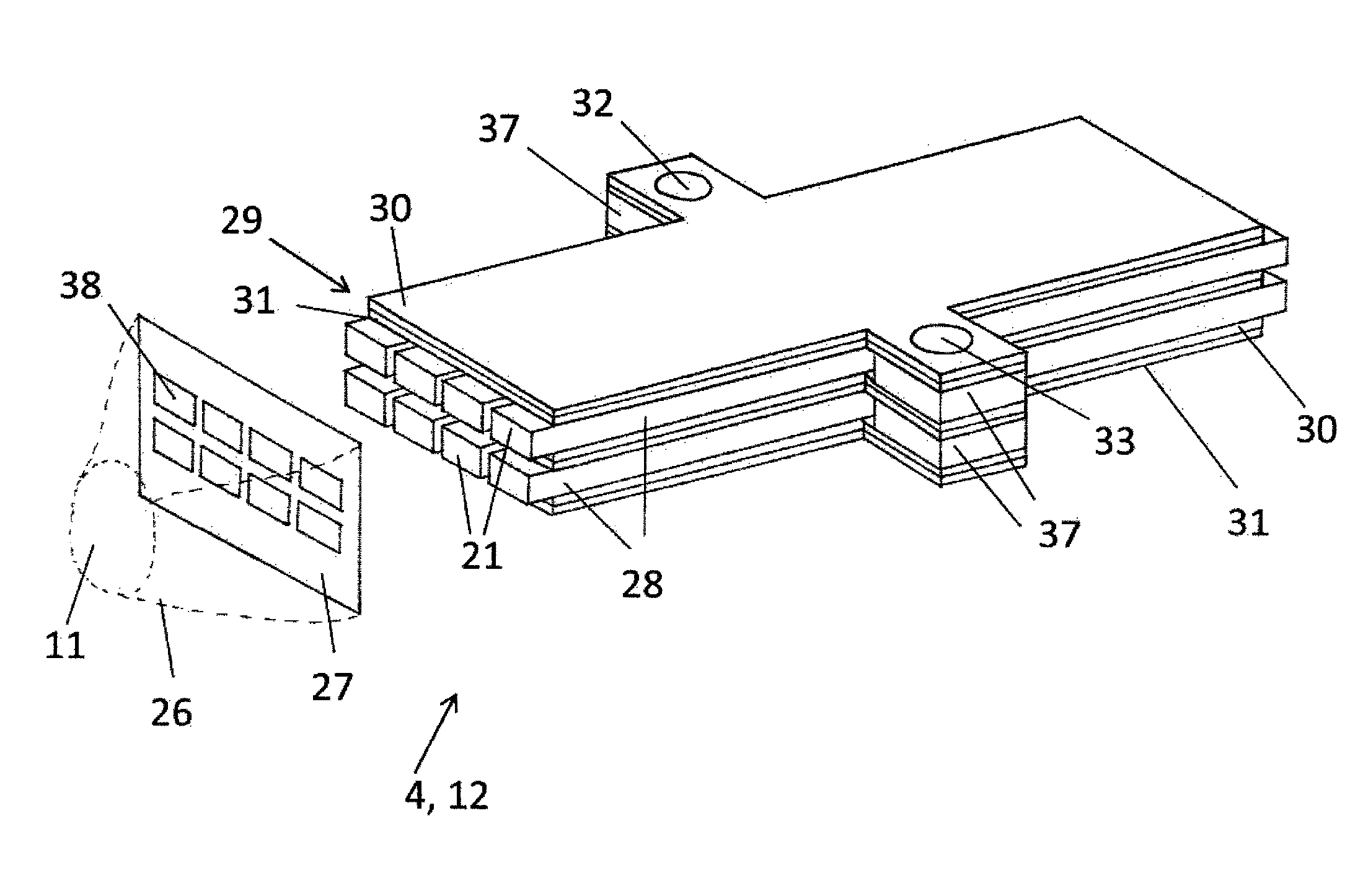
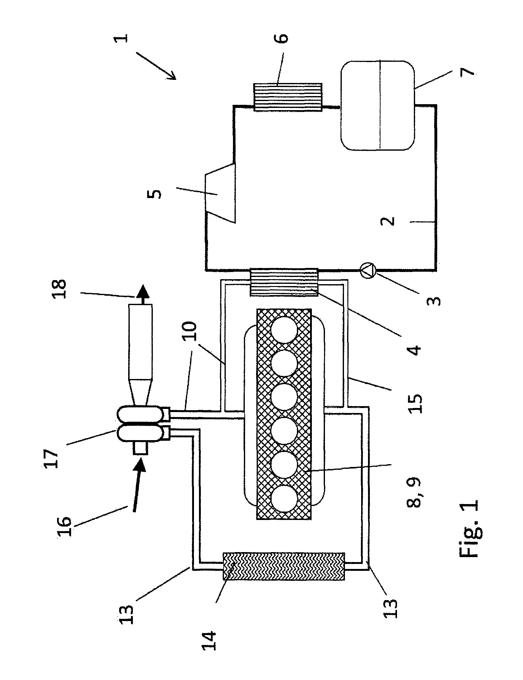
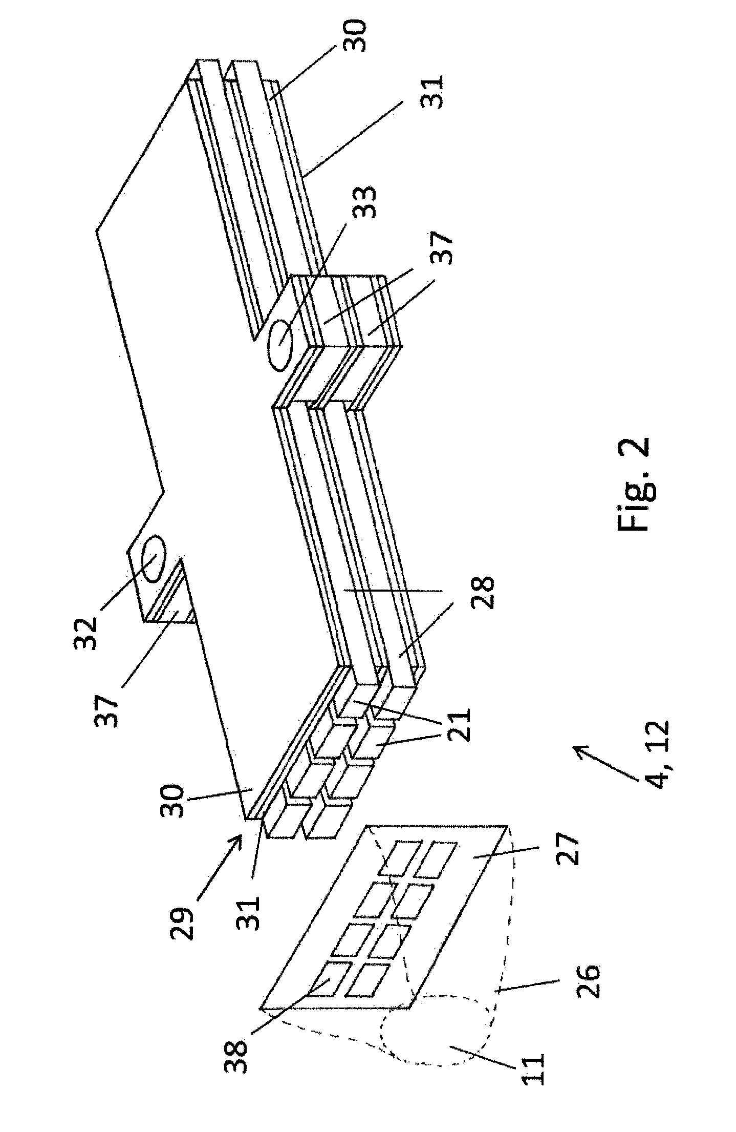
[0036]An internal combustion engine 8 as an internal combustion reciprocating piston engine 9 is used to drive a motor vehicle, particularly a truck, and comprises a system 1 for utilizing waste heat from the internal combustion engine 8 by means of the Clausius-Rankine cycle process. Internal combustion engine 8 has an exhaust turbocharger 17. Exhaust turbocharger 17 compresses fresh air 16 in a charge air line 13 and a charge air cooler 14, built into charge air line 13, cools the charge air before it is supplied to internal combustion engine 8. A portion of the exhaust gas is conducted away from internal combustion engine 8 through an exhaust gas line 10 and then cooled in an evaporator heat exchanger 4 or heat exchanger 12 as an EGR cooler and with an EGR line 15 combined with the fresh air supplied to internal combustion engine 8 with charge air line 13. Another portion of the exhaust gas is introduced into exhaust turbocharger 17, in order to drive exhaust turbocharger 17 and ...


PUM


Abstract

A heat exchanger is provided that includes plate pairs stacked one above the other. A first flow chamber is formed between the two plates of a plate pair by conducting a first fluid therethrough, a second flow chamber for conducting a second fluid therethrough, wherein the second flow chamber is formed between two adjacent plate pairs, an inlet opening for introducing the first fluid, and an outlet opening for discharging the first fluid. The plates have at least one expansion opening, in particular at least one expansion slit, for reducing stress in the plates. The heat exchanger can withstand high thermal and mechanical loads even over a long time period, such as 10 years.

Description

[0001]This nonprovisional application is a continuation of International Application No. PCT / EP2011 / 067515, which was filed on Oct. 6, 2011, and which claims priority to German Patent Application No. DE 10 2010 042 068.9, which was filed in Germany on Oct. 6, 2010, and which are both herein incorporated by reference.BACKGROUND OF THE INVENTION[0002]1. Field of the Invention[0003]The present invention relates to a heat exchanger, a system for utilizing the waste heat from an internal combustion engine via a Clausius-Rankine cycle process, and an internal combustion engine having a system for utilizing the waste heat of the internal combustion engine by the Clausius-Rankine cycle process.[0004]2. Description of the Background Art[0005]Internal combustion engines are used in various technical applications for converting thermal energy into mechanical energy. In motor vehicles, especially in trucks, internal combustion engines are used to move the motor vehicle. The efficiency of intern...

Claims


Application Information

Patent Timeline
Patent Type & Authority Patents(United States)
IPC IPC(8): F01K23/10F28F3/08F01K7/16F01K23/06F28D7/00F28D9/00F28D21/00
CPCF28F3/08F01K23/065F01K7/16F28D7/0025F28D9/0043F28D21/0003F28D2021/0085F28F2265/26F28D7/00F28D9/00
Inventor IRMLER, KLAUS
Owner BEHR GMBH & CO KG
Why Eureka
Try Eureka