Method and device for detecting a replacement of pencil glow plugs in an internal combustion engine

a technology of glow plugs and pencils, which is applied in the direction of machines/engines, mechanical equipment, instruments, etc., can solve the problems of difficult to evaluate them accurately, and achieve the effects of detecting more robustly, reducing current and power consumption, and reducing the difficulty of detecting accuracy

Inactive Publication Date: 2014-09-09
ROBERT BOSCH GMBH
View PDF13 Cites 4 Cited by
  • Summary
  • Abstract
  • Description
  • Claims
  • Application Information

AI Technical Summary

Benefits of technology

[0006]The underlying object of the invention is thus to describe a method and an apparatus for detecting a replacement of sheathed-element glow plugs in an internal combustion engine, which enable accurate detection of the replacement of the sheathed-element glow plug independently of environmental conditions.
[0007]According to the present invention, the object is achieved in that in the driving cycle, the same electrical parameter is determined for all sheathed-element glow plugs installed in the internal combustion engine, these electrical parameters of the sheathed-element glow plugs behaving in a specific pattern with respect to one another, and this pattern of the electrical parameter of the sheathed-element glow plugs being compared with a pattern that was ascertained in a preceding driving cycle, a replacement of a sheathed-element glow plug being detected if the pattern of the driving cycle deviates from a pattern of the preceding driving cycle. This means that if a sheathed-element glow plug has a higher current value and / or power value at full load as compared with another sheathed-element glow plug, it must have a higher current value and / or power value than the other sheathed-element glow plug at idle as well. This continuity in the electrical parameters is evaluated in order to detect the replacement of the sheathed-element glow plugs. This has the advantage that a considerable improvement is achieved in terms of the robustness with which the replacement of the sheathed-element glow plugs is detected.
[0008]Advantageously, the pattern of the sheathed-element glow plugs is determined by way of the orders of magnitude of the electrical parameter measured at the various sheathed-element glow plugs. Consideration of the respective magnitude ratio, which is maintained in every operating state, makes it possible to detect particularly easily which individual plug has been exchanged.
[0010]In a further development, the pattern of the electrical parameters of the sheathed-element glow plugs is stored over multiple driving cycles, and a plug replacement is detected from the discontinuity of the pattern with the stored pattern. As a result, present deviations can be compared with a history, so that a natural aging profile of the sheathed-element glow plugs can be blocked out.
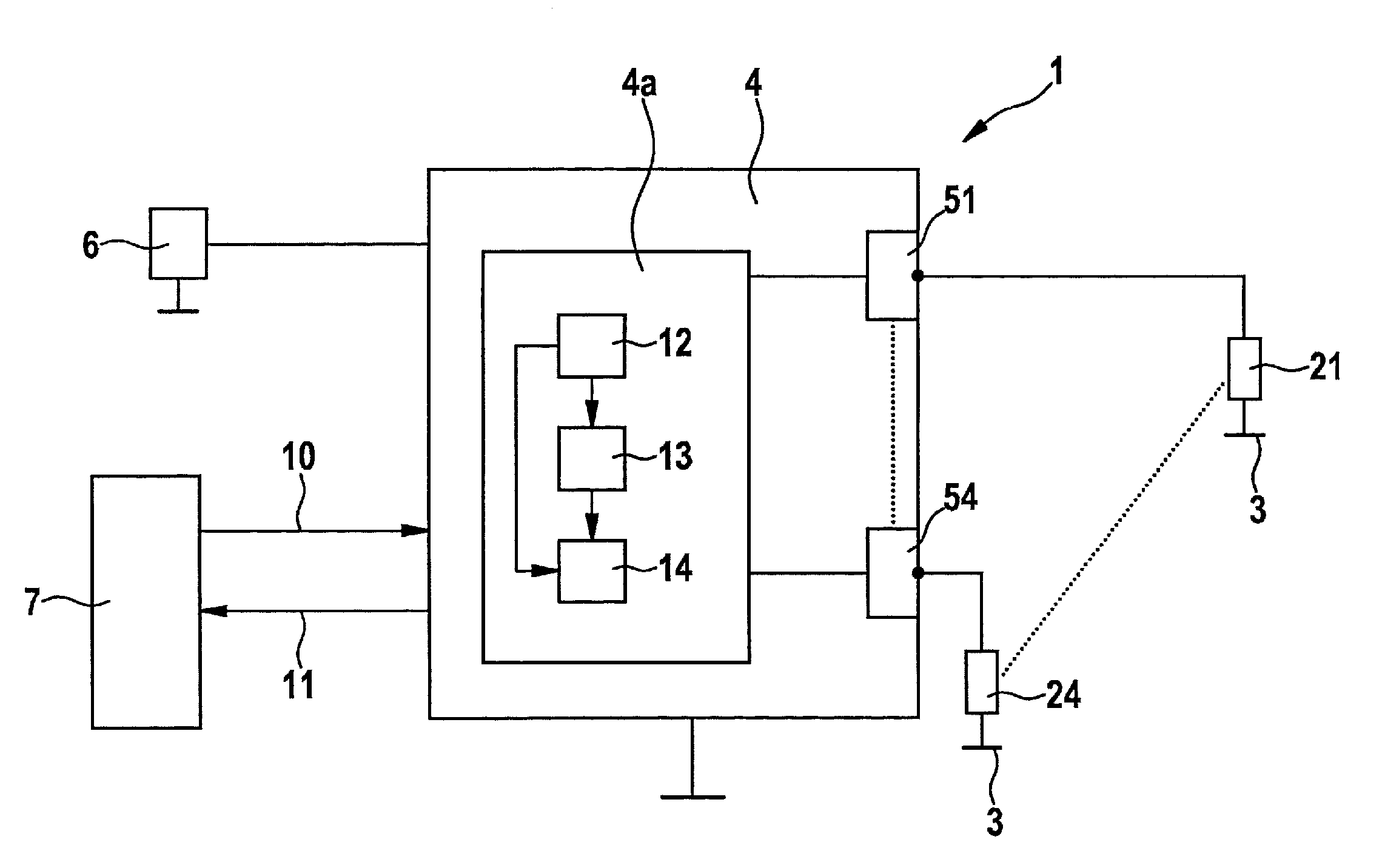
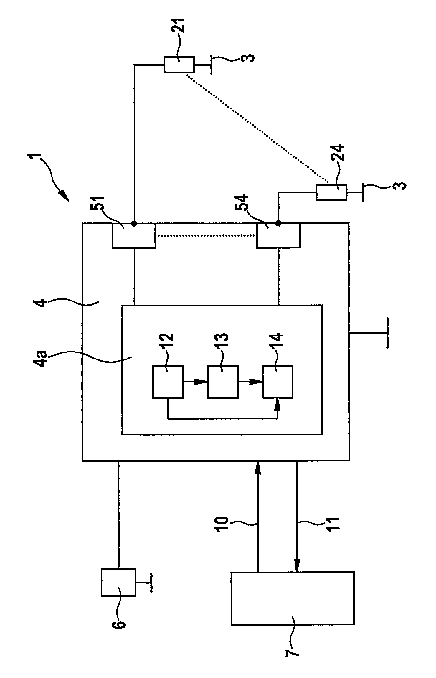
[0013]In a further development, the invention relates to an apparatus for detecting the replacement of sheathed-element glow plugs in an internal combustion engine, having a measurement unit for measuring at least one electrical parameter of a sheathed-element glow plug and a memory unit for storing the at least one electrical parameter of a sheathed-element glow plug. In an apparatus that furnishes an accurate result of the identification of the replacement of the sheathed-element glow plug independently of environmental conditions, the measurement unit measures at least one electrical parameter of all sheathed-element glow plugs installed in the internal combustion engine, and the memory unit stores the measured values of the at least one electrical parameter of all sheathed-element glow plugs, and a pattern recognition unit connected to the measurement unit and to the memory unit determines the pattern that is constituted by the at least one electrical parameter of all sheathed-element glow plugs and compares it with the pattern resulting from the stored values of the at least one parameter of the sheathed-element glow plugs, and detects a replacement of a sheathed-element glow plug if the pattern of the measured values deviates from the pattern of the stored values. Evaluation of the pattern has, in this context, the advantage that if a sheathed-element glow plug has a lower current and power consumption as compared with another sheathed-element glow plug, for example, at idle, it has a lower current and power consumption as compared with the other sheathed-element glow plug under full load as well, regardless of the actual absolute value. Replacement can thus be detected more robustly by comparing the pattern of the current and power consumption of the sheathed-element glow plugs among one another, than if each plug is merely compared by itself. Because different plug types having the same geometrical dimensions exist, incorrectly installed sheathed-element glow plugs with an incorrectly applied voltage can be immediately detected. This incorrectly applied voltage results in an incorrect plug temperature, with the consequence that if the sheathed-element glow plug becomes too hot, it is destroyed; this can result in engine damage. If the sheathed-element glow plug is too cold, this has a negative influence on the combustion behavior of the engine. Evaluation of the pattern allows such deleterious effects to be reliably suppressed. In addition, a service person need not actively communicate plug replacement to an engine control unit and / or glow time control unit that executes sheathed-element glow plug control. Software algorithms that are based on the aging-related behavior of the individual-plug parameters can react correctly to the sheathed-element glow plug replacement, and do not cause malfunctions.

Problems solved by technology

Because these individual-plug current, resistance, and / or electrical-power profiles greatly depend on environmental conditions, it is difficult always to evaluate them accurately, since the environmental conditions cannot always necessarily be set identically in the various driving cycles.

Method used


Image

  • Method and device for detecting a replacement of pencil glow plugs in an internal combustion engine
  • Method and device for detecting a replacement of pencil glow plugs in an internal combustion engine

Examples


Embodiment Construction

[0015]At ambient temperatures below 40° C., cold internal combustion engines, in particular diesel engines, require a starting aid in order to ignite the fuel-air mixture introduced into the internal combustion engine. Glow plug systems, which are made up of sheathed-element glow plugs, a glow time control unit, and a glow plug software program that is stored in an engine control unit or in the glow time control unit, are used as a starting aid. In addition, glow plug systems are also used to improve the vehicle's emissions. Further areas of utilization of the glow plug system are in the burner exhaust gas system, for auxiliary heating, fuel preheating, or coolant water preheating.

[0016]FIG. 1 shows a glow plug system of this kind in which multiple sheathed-element glow plugs 2 to 24 are present, each sheathed-element glow plug 21 to 24 projecting into a respective cylinder of a combustion chamber (not further depicted) of the internal combustion engine. Sheathed-element glow plugs ...


PUM


Abstract

In a method for detecting a replacement of sheathed-element glow plugs in an internal combustion engine, an electrical parameter of the sheathed-element glow plug is determined during a driving cycle and is compared with a stored value of the same electrical parameter of the sheathed-element glow plug that was determined in a preceding driving cycle. In the driving cycle, the same electrical parameter is determined for all sheathed-element glow plugs installed in the internal combustion engine, and the determined pattern of the electrical parameter is compared with a pattern that was ascertained in a preceding driving cycle, a replacement of a sheathed-element glow plug being detected if the pattern of the driving cycle deviates from a pattern of the preceding driving cycle.

Description

BACKGROUND OF THE INVENTION[0001]1. Field of the Invention[0002]The present invention relates to a method for detecting a replacement of sheathed-element glow plugs in an internal combustion engine, in which at least one electrical parameter of the sheathed-element glow plug is determined during a driving cycle and is compared with a stored value of the same electrical parameter of the sheathed-element glow plug that was determined in a preceding driving cycle; and to an apparatus for carrying out the method.[0003]2. Description of the Related Art[0004]Published German patent application document DE 10 2008 007 398 A1 discloses a method and an apparatus for detecting the replacement of sheathed-element glow plugs in an internal combustion engine, in which, at the beginning of a driving cycle, at least one electrical characteristic value of at least one sheathed-element glow plug is measured, a present value of that characteristic value is determined and is compared with at least one...

Claims


Application Information

Patent Timeline
Patent Type & Authority Patents(United States)
IPC IPC(8): G01M15/04F02P17/00F02P19/02
CPCG01M15/042F02P19/02F02P19/027F02P17/00F02P19/025
Inventor MORITZ, RAINERSTOCKMANN, DIRKSCHOLTEN, CARSTENKAPPELMANN, PETER
Owner ROBERT BOSCH GMBH
Why Eureka
Try Eureka