Connection assembly for joining a turbine housing and a bearing housing and exhaust gas turbocharger

a technology of bearing housing and turbine housing, which is applied in the direction of liquid fuel engines, motors, jet propulsion plants, etc., can solve the problems of exhaust gas entering the environment and not flowing through the turbine housing, and achieve the effect of no emissions and only affecting costs

Inactive Publication Date: 2014-09-09
IHI CHARGING SYST INT
View PDF10 Cites 16 Cited by
  • Summary
  • Abstract
  • Description
  • Claims
  • Application Information

AI Technical Summary

Benefits of technology

[0014]Such an arrangement provides for an advantageous positioning of the heat shield and of the sealing arrangement, whereby a gas leak is prevented. Thus, no exhaust gas flowing through the turbine housing and driving a turbine of the exhaust gas charger can escape to the environment without being treated in an exhaust gas aftertreatment system. The exhaust gas is contained in the exhaust gas turbocharger and is passed through a corresponding exhaust gas piping to the exhaust gas aftertreatment system, where it is cleaned and only then flows to the environment via an exhaust pipe.
[0034]The use of the connection assembly according to the invention in an exhaust gas turbocharger of an internal combustion engine proves to be extremely advantageous, as undesired emissions of uncleaned exhaust gas and thus an additional contamination of the environment, for example by an increased NO emission can be avoided.

Problems solved by technology

Thus, no exhaust gas flowing through the turbine housing and driving a turbine of the exhaust gas charger can escape to the environment without being treated in an exhaust gas aftertreatment system.

Method used


Image

  • Connection assembly for joining a turbine housing and a bearing housing and exhaust gas turbocharger
  • Connection assembly for joining a turbine housing and a bearing housing and exhaust gas turbocharger
  • Connection assembly for joining a turbine housing and a bearing housing and exhaust gas turbocharger

Examples


Embodiment Construction

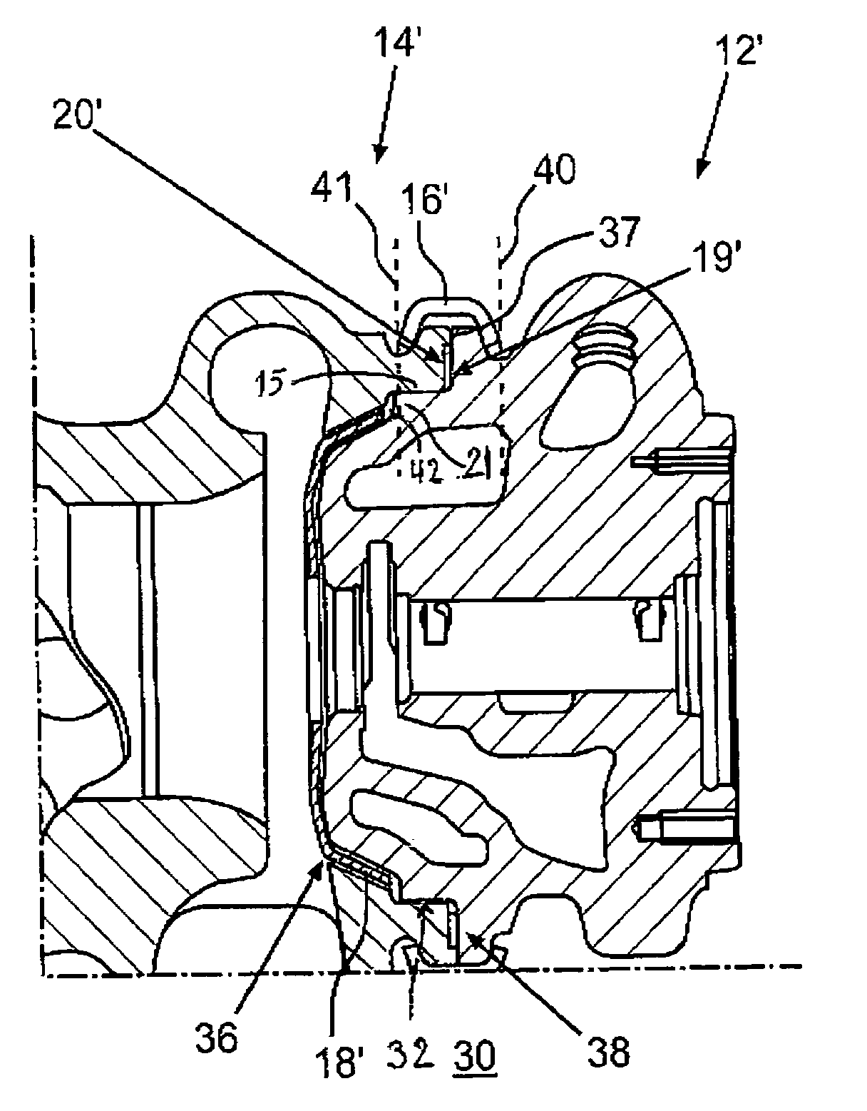
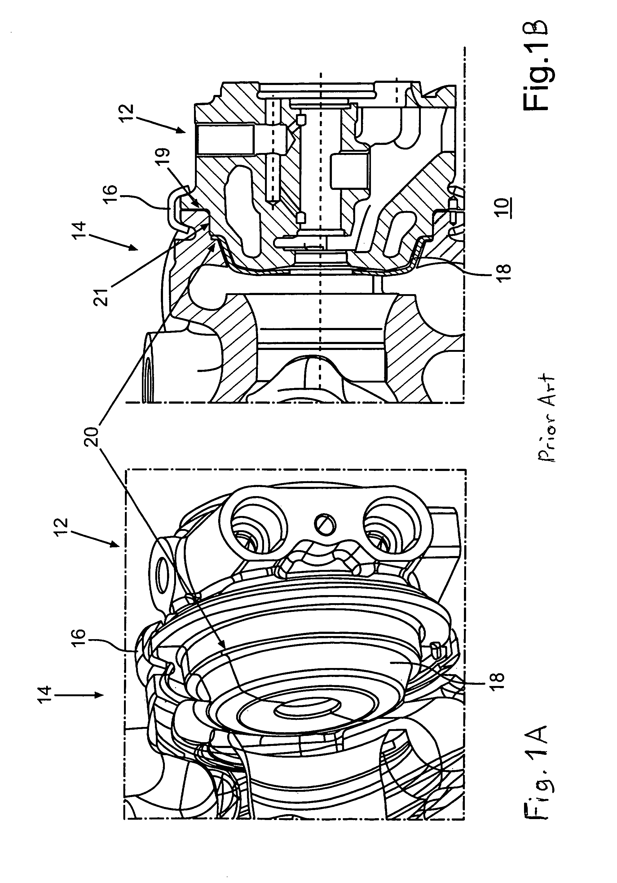
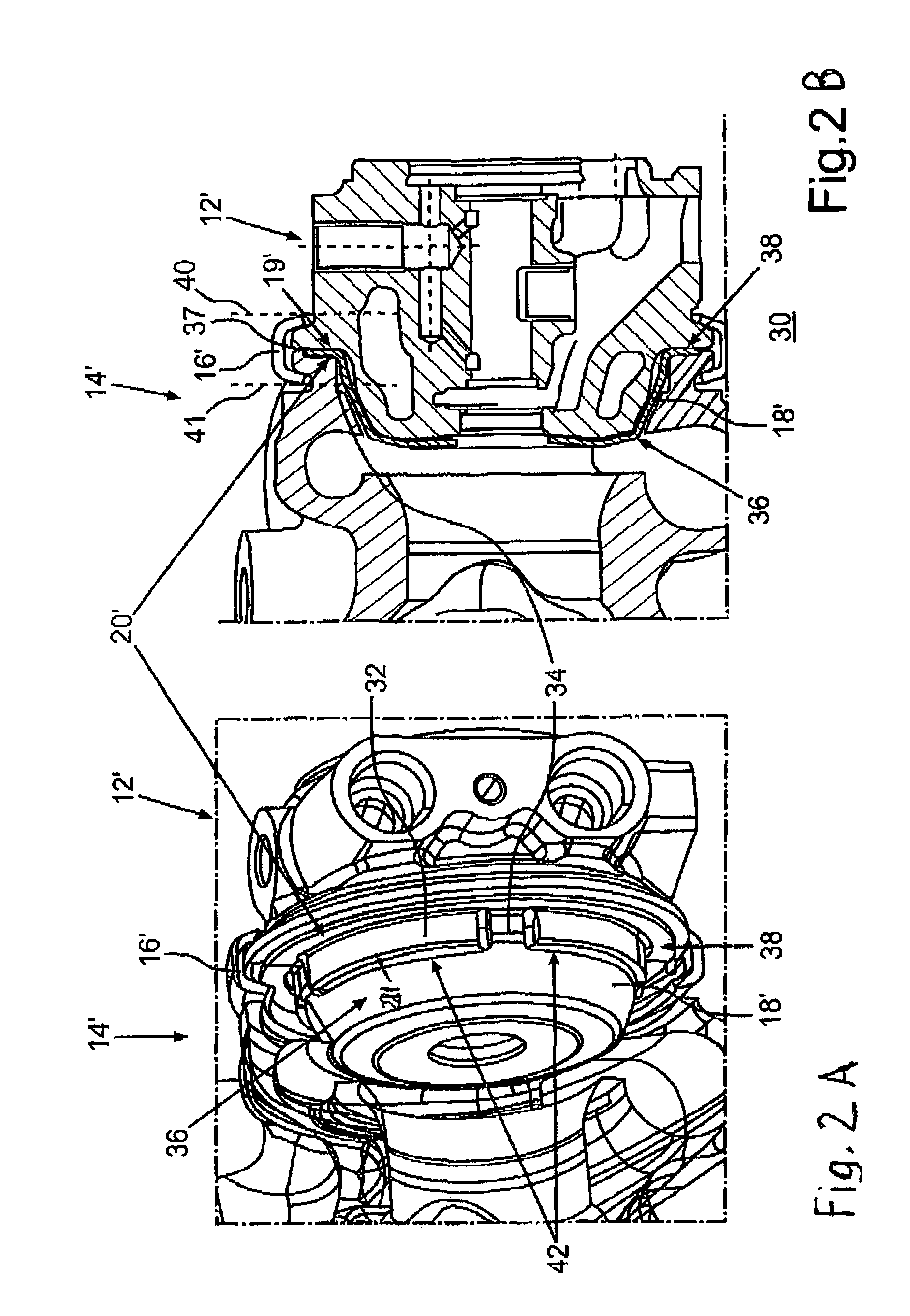
[0039]While FIGS. 1A, 1B show a connection assembly of a turbine housing to a bearing housing of an exhaust gas turbocharger according to the state of the art with a heat shield and a sealing assembly of the bearing housing, the turbine housing and the heat shield are positioned adjacent to each other in the axial direction of the turbine housing and thus outside a connection device. FIGS. 2A, 2B slow a connection assembly of a turbine housing to a bearing housing of an exhaust gas turbocharger. The sealing assembly is positioned centered relative to a connection element and thus to the housings. FIGS. 3A, 3B show the connection assembly of FIGS. 2A, 2B, wherein the longitudinal section is shown in a rotationally displaced axial plane of the connection assembly, so that further aspects of the connection assembly of FIGS. 2B and 3B are shown.

[0040]FIGS. 2A, 2B show a connection assembly 30, wherein a bearing housing 12′ is connected to a turbine housing 14′ by means of a connection d...


PUM


Abstract

In a connection assembly of a turbine housing to a bearing housing of an exhaust gas turbocharger and to an exhaust gas turbocharger, wherein the turbine housing and the bearing housing are centered relative to each other and connected to each other in the region of a connection joint including a sealing assembly with a heat shield disposed between the turbine housing and the bearing housing, at least one cutout is provided in the heat shield for accommodating a centering means by way of which the turbine housing and the bearing housing are directly centered relative to one another.

Description

[0001]This is a Continuation-In-Part application of pending international patent application PCT / EP2010 / 000164 filed Jan. 14, 2010 and claiming the priority of German patent application 10 2009005 013.2 filed Jan. 17, 2009.BACKGROUND OF THE INVENTION[0002]The invention relates to a connection assembly of a turbine housing with a bearing housing of an exhaust gas turbocharger and to an exhaust gas turbocharger including such a connection assembly.[0003]Such a connection assembly is already known and is shown in FIG. 1. FIG. 1 shows a known connection assembly 10 of a turbine housing 14 to a bearing housing 12 of an exhaust gas turbocharger. The turbine housing 14 is thereby centered on the bearing housing 12 by means of a centering collar 21.[0004]When connecting the two housings by means of a V collar clamp 16, a connection joint 19 is obtained, which of course needs a seal.[0005]The sealing of the connection joint 19 is realized in such a manner that the turbine housing 14 and the ...

Claims


Application Information

Patent Timeline
Patent Type & Authority Patents(United States)
IPC IPC(8): F01D25/16F02C6/12F02C7/24
CPCF02C7/24F02C6/12F05D2230/642F05D2220/40
Inventor DELITZ, JOACHIM
Owner IHI CHARGING SYST INT
Why Eureka
Try Eureka