
Laser-protective wall element for a housing in laser machining stations

a technology of laser machining station and protective wall element, which is applied in the direction of laser beam welding apparatus, burglar alarm short radiation actuation, instruments, etc., can solve the problems of correspondingly high effort and/or expense, inability to ensure 100% security, and high and cost-intensive material use, etc., and achieves a very small amount of security. , no loss of security

Active Publication Date: 2014-09-09
FRAUNHOFER GESELLSCHAFT ZUR FOERDERUNG DER ANGEWANDTEN FORSCHUNG EV
View PDF14 Cites 7 Cited by
  • Summary
  • Abstract
  • Description
  • Claims
  • Application Information

AI Technical Summary

Benefits of technology

[0036]The advantages of active protection come into effect with the laser protective wall in accordance with the invention. Nevertheless, however, a single deposition of laser radiation onto a position of the housing at least does not result in a total failure of the functionality, even if the intermediate layer has been destroyed or damaged at this position so that hot conductor properties are no longer present there. Other surface regions are then still functional and the housing can continue to be utilized with security which is limited extremely slightly. A complex and / or expensive repair or even replacement is only required with a large-area impairment.
[0037]Some materials, substances or substance mixtures which can be used for intermediate layers, however, also remain resistant at a high degree of heating and maintain their properties so that no loss in security can be noted.

Problems solved by technology

As a rule, only a visual examination takes place in this respect subsequent to a machining with laser radiation which has to be carried out at more or less wide time intervals, which causes a correspondingly high effort and / or expense and no 100% security can be ensured.
Sufficiently secure protective walls and required support constructions therefore have to be manufactured with a high and cost-intensive use of material.
It is obvious in this respect that the leak tightness is in particular problematic when an underpressure is present in such hollow spaces or when a fluid is contained in them.
If such an electrical conductor is parted as a consequence of melting, electrical current can no longer flow, which should then result in a deactivation of the laser.
It is very complex and / or expensive in this respect to form the electrical conductors and in so doing accepting losses which are as small as possible.
Even if the electrical conductors are designed in meandering form, gaps, that is, regions in which no electrical conductor is present, cannot be avoided, which is also critical with small beam cross-sections of high-power lasers which on incidence do not cause a parting of such an electrical conductor with sufficient security.
After parting an electrical conductor, this system is no longer operable and the security is only present again after replacement or complex and / or expensive repair.

Method used


Image

  • Laser-protective wall element for a housing in laser machining stations
  • Laser-protective wall element for a housing in laser machining stations
  • Laser-protective wall element for a housing in laser machining stations

Examples


Embodiment Construction

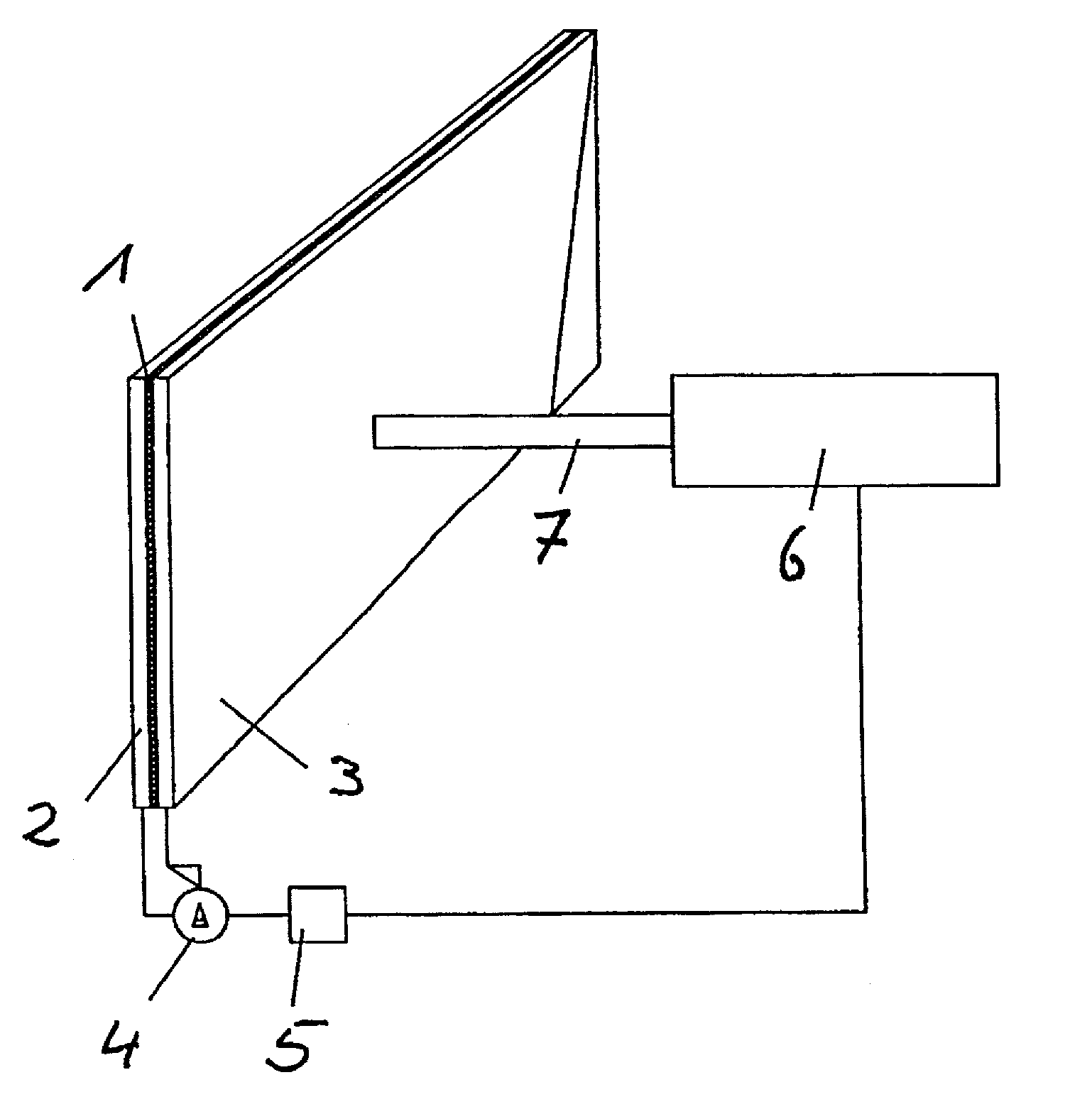
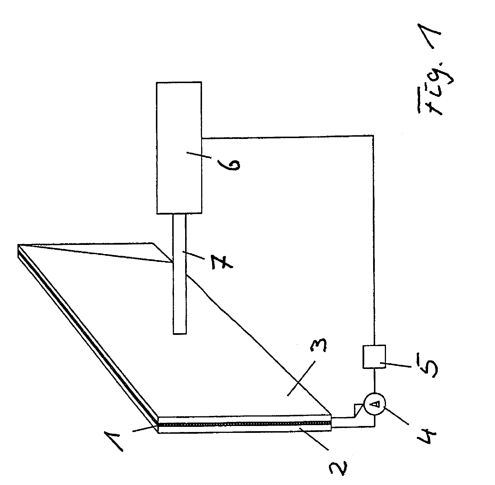
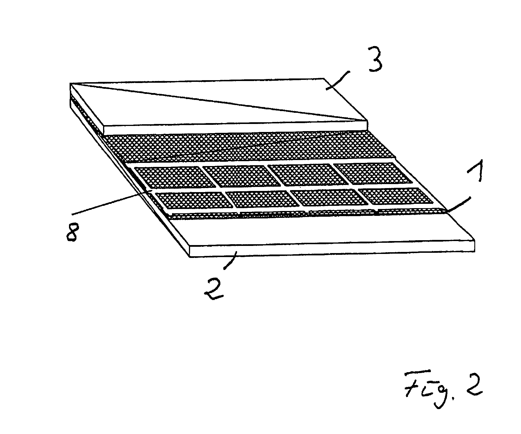
[0043]In the laser protective wall element shown in FIG. 1, which can be used at an example of a housing in laser machining stations, two metal sheets formed from zinc-plated steel are connected to one another with material continuity and over the full area as electrically conductive plate-like elements 2 and 3 by a binder which has hot conductor properties. The binder forms the intermediate layer 1. A binder which is available from POLYTEC PT GmbH, Waldbronn, Del., under the trade name Resbond 906, was used as the binder. The thus formed intermediate layer 1 had a thickness between the two plate-like elements 2 and 3 of 1 mm±0.5 mm. In addition, a glass fabric is embedded in the intermediate layer 1 as a spacer. The steel metal sheets, as plate-like elements 2 and 3, have dimensions of 1000 mm×1000 mm×1 mm.

[0044]An electrical voltage to the amount of 24 V was applied to the two steel metal sheets, as plate-like elements 2 and 3, and the flow of the electrical current between the tw...


PUM

PropertyMeasurementUnit
temperatureaaaaaaaaaa
thicknessaaaaaaaaaa

Abstract

A laser protective wall element for a housing in laser machining stations with which increased protection, in particular for the eyes of living beings, can be achieved. In a laser protective wall element for a housing at laser machining stations, an intermediate layer is present which has hot conductor properties. The intermediate layer can be formed between electrically conductive plate-like elements, an electrically conductive plate-like element and an electrically conductive coating or also two electrically conductive layers or can be arranged there. The electrically conductive plate-like elements, the coating and/or the layers are connected to an electrical voltage source as well as a measuring instrument which detects electrical current, electrical resistance and/or electrical capacity and whose measured signal change can be used for the condition monitoring of the laser protective wall element.

Description

FIELD OF INVENTION[0001]The invention relates to a laser protective wall element for a housing in laser machining stations with which increased protection, in particular for the eyes of living beings, can be achieved.BACKGROUND INFORMATION[0002]In the past, the demands on protective equipment against laser radiation in laser machining was increased, which was in particular the case as the result of the increased beam qualities and power densities achievable with fiber lasers and disc lasers.[0003]A distinction is made between passive protective equipment and active protective equipment in this respect. With passive protective equipment, changes in or the destruction of materials are registered which occur as a result of the energy conversion into heat. In this respect, as a rule, penetration of wall elements provided for this purpose can also occur. As a rule, only a visual examination takes place in this respect subsequent to a machining with laser radiation which has to be carried...

Claims


Application Information

Patent Timeline
Patent Type & Authority Patents(United States)
IPC IPC(8): G01R31/00B23K26/30F16P1/06
CPCB23K26/427F16P1/06B23K26/706
Inventor HANNWEBER, JANKUEHN, STEFANBRETSCHNEIDER, SVENMELDE, MICHAEL
Owner FRAUNHOFER GESELLSCHAFT ZUR FOERDERUNG DER ANGEWANDTEN FORSCHUNG EV
Learn More