Fuel lances having thermally insulating coating

Inactive Publication Date: 2016-01-14
SIEMENS AG
View PDF8 Cites 0 Cited by
  • Summary
  • Abstract
  • Description
  • Claims
  • Application Information

AI Technical Summary

Benefits of technology

[0011]This means for example that, if the first surface location experiences greater heat input than the second surface location, the thermal insulation layer applied to the first surface location should have a greater layer thickness than the thermal insulation layer applied to the second surface location, and vice versa. This offers the advantage that the temperature distribution in the tip of the fuel lance is homogenized in a particularly effective manner, whereby the temperature gradients are reduced to a particularly great extent. The invention however also encompasses embodiments in which the thermal insulation layer is applied with a substantially constant layer thickne

Problems solved by technology

In this way, it is often the case that, at the tip of the fuel lance, steep temperature gradients arise which lead to mechanical stresses and ultim

Method used


Image

  • Fuel lances having thermally insulating coating
  • Fuel lances having thermally insulating coating
  • Fuel lances having thermally insulating coating

Examples


Example

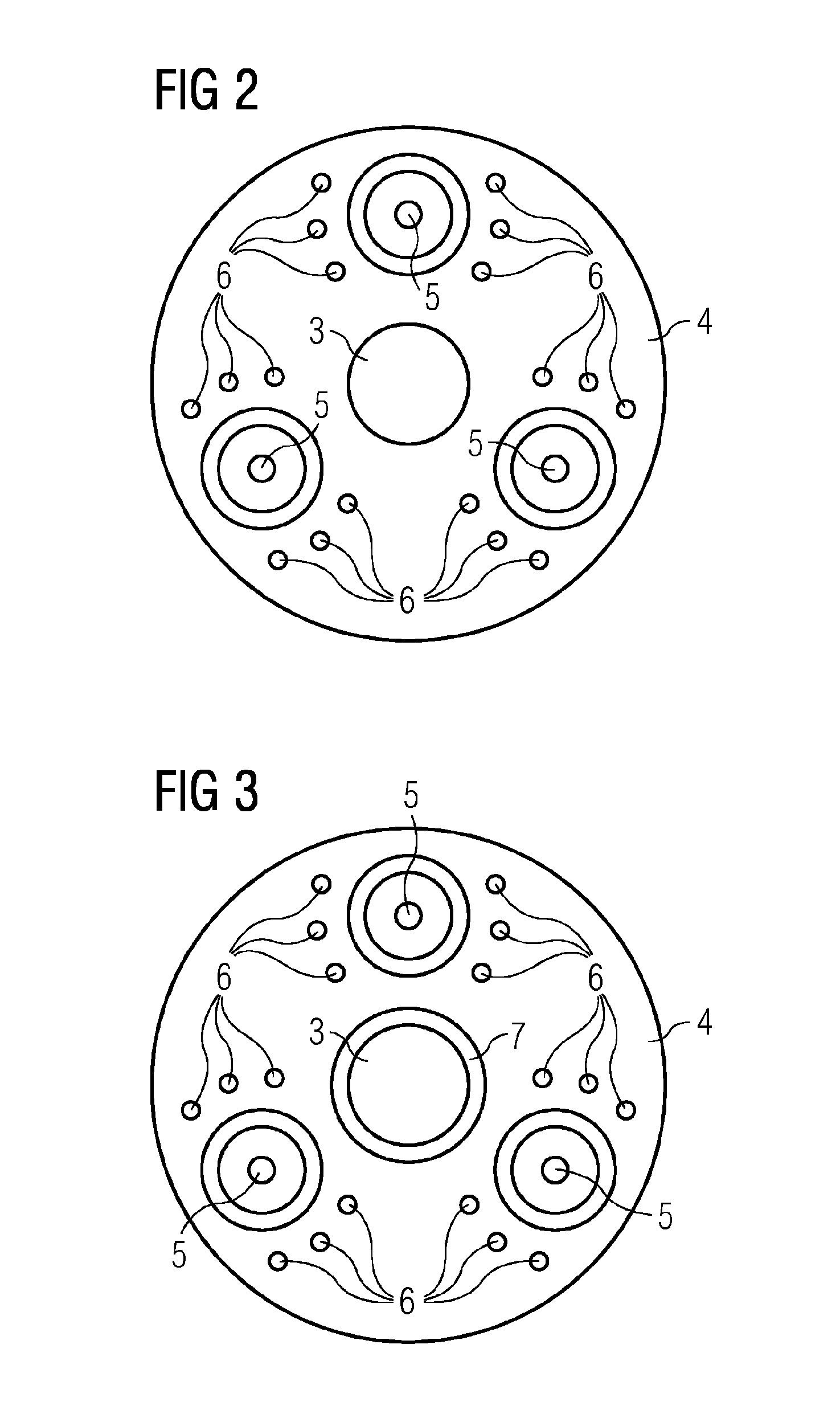
[0038]FIG. 3 shows a first embodiment of the fuel lance according to the invention. The fuel lance according to the invention is of substantially the same construction as the conventional fuel lances of FIGS. 1 and 2. Said fuel lance however additionally has a thermal insulation layer 7 or 8 arranged on the nozzle surface 4, said thermal insulation layer being arranged annularly around the outlet opening 3 in the exemplary embodiment of FIG. 3. This arrangement, while yielding a minimal surface area of the thermal insulation layer 7, protects the most sensitive region of the tip of the fuel lance 1, which is situated between the outlet opening 3 and the fuel nozzles 5.

Example

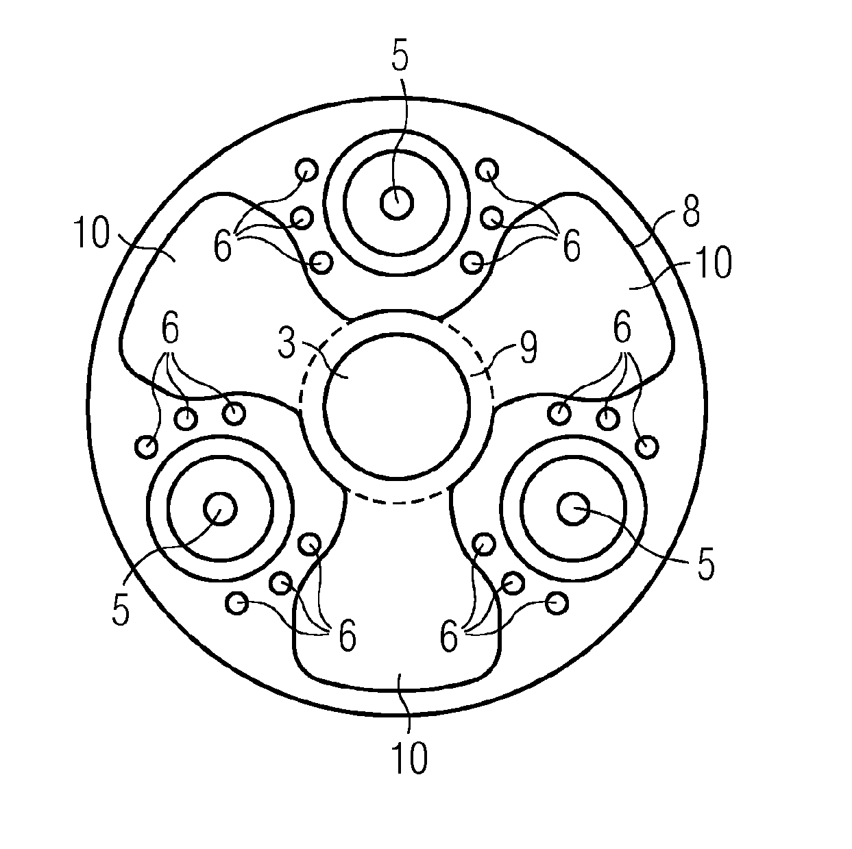
[0039]FIG. 4 shows a second embodiment of the fuel lance according to the invention, in which the thermal insulation layer 8 is applied both to the region 9 between the outlet opening 3 and the fuel nozzles 5 as in the case of the first exemplary embodiment, and in the form of projections 10, which are particularly provided in a number corresponding to the number of fuel nozzles 5 and which are each arranged between two adjacent fuel nozzles 5, to the regions between the fuel nozzles 5. In the drawing, the annular region 9, which corresponds to that of the thermal insulation layer 7 in the example of FIG. 3, is separated from the projections 10 by way of a dashed line in order to provide a clearer illustration. In reality, the thermal insulation layer 8 is however advantageously of unipartite and continuous form.

[0040]In all of the embodiments of the invention that are shown, a layer thickness of the thermal insulation layers 7 and 8 may spatially vary, as has already been discussed...


PUM

PropertyMeasurementUnit
Thicknessaaaaaaaaaa
Threshold limitaaaaaaaaaa
Thermal propertiesaaaaaaaaaa

Abstract

A method for producing a fuel lance for a burner, in particular for a gas turbine burner, has at least the following steps: creating a fuel lance body having a tip that has a cooling air duct, which opens into an exit opening extending around a longitudinal axis of the fuel lance body, and a nozzle face, which is arranged around the exit opening and has a plurality of fuel nozzles; determining a spatial distribution of a heat input, to which the nozzle face is subjected during operation when a fuel flowing out through the fuel nozzles is burnt; and applying a thermally insulating layer onto the nozzle face in accordance with the spatial distribution of the heat input. A fuel lance is produced with the method. A burner has such a fuel lance.

Description

CROSS REFERENCE TO RELATED APPLICATIONS[0001]This application is the US National Stage of International Application No. PCT / EP2014 / 050896 filed Jan. 17, 2014, and claims the benefit thereof. The International Application claims the benefit of German Application No. DE 102013201843.6 filed Feb. 5, 2013. All of the applications are incorporated by reference herein in their entirety.FIELD OF INVENTION[0002]The present invention relates to a method for producing an improved fuel lance, to an improved fuel lance, and to a burner having a fuel lance of said type.BACKGROUND OF INVENTION[0003]Fuel lances are used in burners which can be operated both with liquid fuel and with gaseous fuel. In general, the fuel lance is provided for operation with liquid fuels, for example oil. The liquid fuel flows through the fuel lance and, at the tip thereof, emerges through fuel nozzles into a combustion chamber, with the fuel being atomized. The fuel lances furthermore comprise a cooling air duct throu...

Claims


Application Information

Patent Timeline
IPC IPC(8): F23R3/28B23P15/00
CPCB23P15/00F23R3/283F23C2900/07021F23D2213/00F23D2900/00018F23R2900/00005
Inventor CLOSSEN-VON LANKEN SCHULZ, MICHAELKADAU, KAIKLEINFELD, JENSROLLMANN, GEORGSCHILDMACHER, KAI-UWEOZKAN, KAGAN
Owner SIEMENS AG
Why Eureka
Try Eureka