
Arrangement for coating substrate surfaces by means of electric arc discharge

a technology of electric arc discharge and substrate surface, which is applied in the direction of ion implantation coating, coating, electrical apparatus, etc., can solve the problems of negative consequences, disadvantageous layer properties, and relatively low energies of coating particles

Active Publication Date: 2022-01-04
FRAUNHOFER GESELLSCHAFT ZUR FOERDERUNG DER ANGEWANDTEN FORSCHUNG EV
View PDF10 Cites 0 Cited by
  • Summary
  • Abstract
  • Description
  • Claims
  • Application Information

AI Technical Summary

Benefits of technology

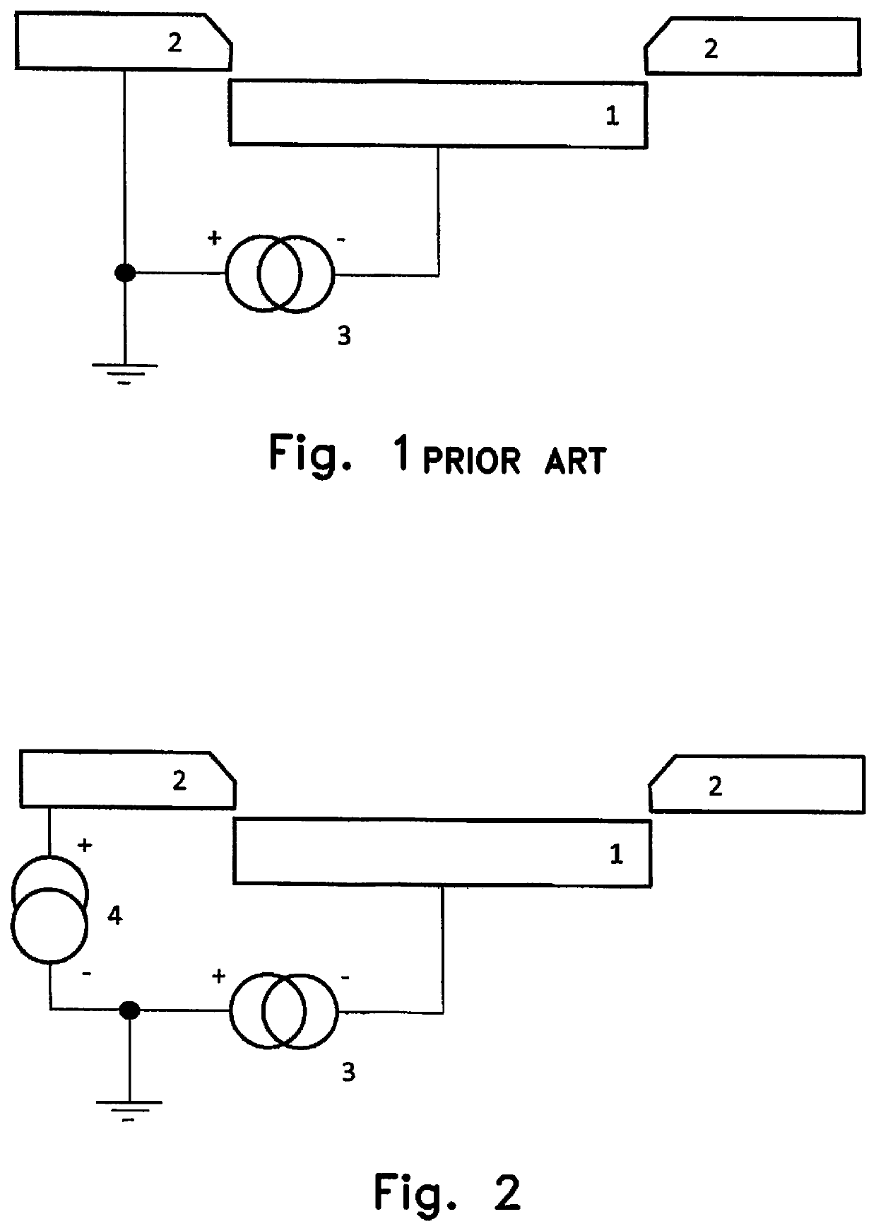
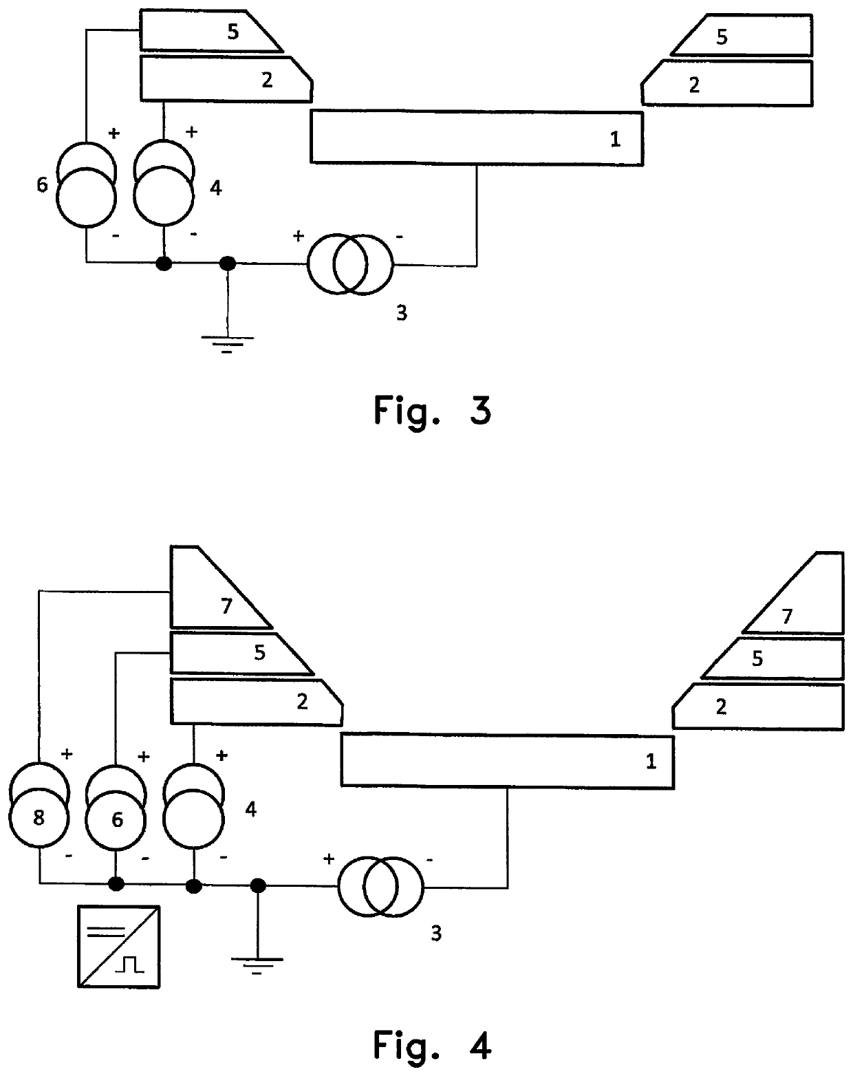
The invention proposes a way to create uniform coatings on surfaces with a constant layer thickness, minimal porosity, and good adhesion. Instead of using a high ionization process, a traditional DC electric arc discharge with moderate electric discharge currents is used. This makes the process applicable to industrial applications. However, the increased ion energy needs to be provided in a different way. This is done by introducing one or more additional electric anode voltage potentials to increase excitation and ionization states. The additionally incorporated anode or anodes result in additional coupling of power into the coating plasma, improved layer quality, and reduced need for an electric bias voltage. Overall, the patent text proposes a solution for creating high-quality coatings on a variety of surfaces.

Problems solved by technology

This can have negative consequences, such as e.g. material removal accompanied by edge rounding and overheating.
The ion energies of the coating particles are comparatively low in these zones; this possibly results in disadvantageous layer properties (e.g. porosity).
However, only a small selection of layer systems is producible using CVD technology.
As a result, the usability of the method is restricted to a very great extent.
This problem cannot be solved satisfactorily by means of traditional PVD methods according to the prior art.
However, the technology used in that case (high-current pulsed arc, HCA, an arc PVD technology using pulsed discharge currents) is very complex and not suitable for industrial tool coatings.

Method used


Image

  • Arrangement for coating substrate surfaces by means of electric arc discharge
  • Arrangement for coating substrate surfaces by means of electric arc discharge
  • Arrangement for coating substrate surfaces by means of electric arc discharge

Examples


example 1

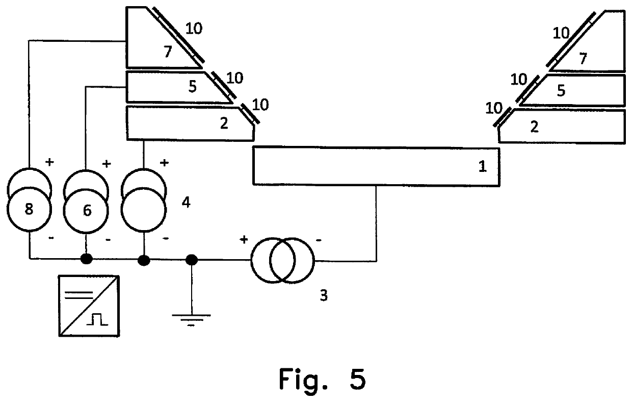
[0051]An arrangement in accordance with FIG. 2 is present, wherein the anode 2 can additionally be covered with a covering 10 composed of graphite in accordance with FIG. 5.

[0052]A process in which metallic substrates are coated with an AlTiOxNy layer is carried out. Firstly, the substrates are chemically cleaned, dried and arranged on mounts in the vacuum chamber. Evacuation to 10−3 Pa is followed by ion cleaning using argon ions. The subsequent coating takes place with the use of a target 1, which is connected as a cathode and is a plate composed of AlTi having the composition (66:33 at %). As reactive gases, a mixture of nitrogen and oxygen in a ratio of 70:30% by volume at a pressure of 1 Pa is fed into the vacuum chamber. With an electric discharge current of 100 A at the electric current source 3 and an electric voltage at the target 1, target material is progressively vaporized by means of an electric arc discharge. The electric voltage of the anode current source 4 is set to...

example 2

[0054]An arrangement in accordance with FIG. 5 is used. A process is carried out in which a forming tool having depressions (cavities) is intended to be coated as substrate. The coating is effected with an AlCrSiN layer. Firstly, the tool is chemically cleaned, dried and arranged in the vacuum chamber such that the coating plasma can reach the working surfaces of the tool. Evacuation to 10−3 Pa is followed by ion cleaning using argon ions. The subsequent coating is carried out with the use of the target 1, which is connected as a cathode and is a plate composed of AlCrSi having the composition (66:29:5 at %). As reactive gas, nitrogen at a pressure of 1 Pa is introduced into the vacuum chamber. With an electric discharge current of 100 A at the current source 3, target material is progressively vaporized by means of an electric arc discharge. The electric voltage of the current source 4 for the first anode 2 is set to 5 V, and the electric voltage at the current source 6, to which t...

example 3

[0057]An arrangement in accordance with FIG. 6 is present. A process is carried out in which complexly shaped tools are intended to be coated. The coating is effected with an AlCrN layer. Firstly, the tools as substrates are chemically cleaned, dried and arranged on rotatable substrate holders (planetary) in the vacuum chamber such that the tools are guided past the target 1, which is connected as a cathode, with constant rotation in three axes. Evacuation to 10−3 Pa is followed by ion cleaning using argon ions. The subsequent coating is carried out with the use of a plate composed of AlCr having the composition (70:30 at %) as the target 1. As reactive gas, nitrogen at a pressure of 1 Pa is introduced into the vacuum chamber. With an electric discharge current of 100 A at the current source 3, to which the target 1 is connected, target material is progressively vaporized by means of an electric arc discharge. The electric voltage of the current source 4, to which the first anode 2 ...


PUM

PropertyMeasurementUnit
positive electric voltage potentialaaaaaaaaaa
distanceaaaaaaaaaa

Abstract

The invention relates to an arrangement for coating substrate surfaces by means of electric arc discharge in a vacuum chamber, wherein electric arc discharges between a target (1) which is electrically connected as a cathode and is formed from a metal material are used. Arranged at a distance from the target (1) is an anode (2), with which the electric arc discharges are ignited to form a plasma formed with metal material of the target (1). The target (1) is connected to a first electric power source (3) and the anode (2) to a second electric power source (4), wherein the absolute values of the electric voltages connected to the target (1) and to the anode (2) different from one another.

Description

BACKGROUND ON THE INVENTION[0001]The invention relates to an arrangement for coating substrate surfaces by means of electric arc discharge. In particular coatings formed with nitride, in particular nitridic coatings, can be advantageously formed on surfaces of substrates.[0002]Vacuum arc technology is a standard technology for depositing thin layers. In the industrial sphere, primarily tools are coated thereby. Typical layer systems are nitridic hard materials such as TiN, AlTiN, CrN, AlCrN, inter alia. The coating is carried out in a vacuum within a chamber. With the aid of an electric arc discharge, a usually metallic material of a target connected as a cathode is vaporized and the resulting vapor is simultaneously ionized. The plasma condenses on the surfaces to be coated and forms a tight thin layer. Addition of reactive gases (e.g. nitrogen) results in a chemical reaction between the plasma and the reactive gas and the layer is formed by the reaction products. In this regard, e...

Claims


Application Information

Patent Timeline
Patent Type & Authority Patents(United States)
IPC IPC(8): H01J37/32C23C14/32C23C14/06
CPCC23C14/325C23C14/0641H01J37/32055H01J37/3255H01J37/32541H01J37/32568H01J37/32614H01J2237/332C23C14/0021C23C14/046H01J37/32064
Inventor ZIMMER, OTMARKAULFUSS, FRANK
Owner FRAUNHOFER GESELLSCHAFT ZUR FOERDERUNG DER ANGEWANDTEN FORSCHUNG EV
Learn More