Display device and method for driving display device

a display device and display technology, applied in the field of display devices, can solve the problems of reducing display quality and visual recognition image quality, and achieve the effect of improving display quality and improving visual recognition image quality

Active Publication Date: 2014-09-09
SHARP KK
View PDF13 Cites 0 Cited by
  • Summary
  • Abstract
  • Description
  • Claims
  • Application Information

AI Technical Summary

Benefits of technology

[0010]In the case of displaying a still image, each pixel repeatedly changes between a bright state and a dark state, and respective images of the individual frames are combined with one another to be visually recognized, with the result that the combined image is free from unevenness and has high display quality. Thus, the still image in FIG. 37, for example, is visually recognized as it is. In the case where an image is scrolled in a lateral direction (that is, a row direction), however, the combined image is, because a viewer's eyes follow the image being scrolled, observed in such a state that a certain pattern appears to be superimposed over the combined image as illustrated in FIG. 39, with the result that the visually recognized image has decreased quality. In the case of (a) of FIG. 40, a certain pattern is superimposed over a combined image at, for example, 2 dots / frame scroll. In the case of (b) of FIG. 40, a certain pattern is superimposed over a combined image at, for example, 1 dot / frame scroll.
[0016]The present invention has been accomplished in view of the above problem with conventional art. It is an object of the present invention to provide (i) a display device and (ii) a display device driving method each of which can provide an arrangement in which, when an image is scrolled, a noise pattern does not easily overlap the image.
[0021]Consequently, the above arrangement advantageously provides a display device which can provide an arrangement in which, when an image is scrolled, a noise pattern does not easily overlap the image.
[0026]Consequently, the above arrangement advantageously provides a display device driving method which can provide an arrangement in which, when an image is scrolled, a noise pattern does not easily overlap the image.
[0029]Consequently, the above arrangement advantageously provides a display device which can provide an arrangement in which, when an image is scrolled, a noise pattern does not easily overlap the image.
[0032]Consequently, the above arrangement advantageously provides a display device driving method which can provide an arrangement in which, when an image is scrolled, a noise pattern does not easily overlap the image.

Problems solved by technology

The above conventional display device that carries out a display with use of a temporal luminance change, however, has been found to have decreased display quality when carrying out a scroll display because a particular noise pattern is superimposed over an image and is recognized as unevenness.
In the case where an image is scrolled in a lateral direction (that is, a row direction), however, the combined image is, because a viewer's eyes follow the image being scrolled, observed in such a state that a certain pattern appears to be superimposed over the combined image as illustrated in FIG. 39, with the result that the visually recognized image has decreased quality.

Method used


Image

  • Display device and method for driving display device
  • Display device and method for driving display device
  • Display device and method for driving display device

Examples


Embodiment Construction

[0073]An embodiment of the present invention is described below with reference to FIGS. 1 through 38.

(Arrangement of Display Device)

[0074]FIG. 3 illustrates a configuration of a liquid crystal display device (display device) 11 of the present embodiment.

[0075]The liquid crystal display device 11 is a display device of a matrix type, in particular of an active matrix type in the present embodiment. The liquid crystal display device includes: an LCD panel 12; a data driver 13; and a display control circuit 14. The display control circuit 14 includes: a γ switching circuit 14a; and a memory 14b.

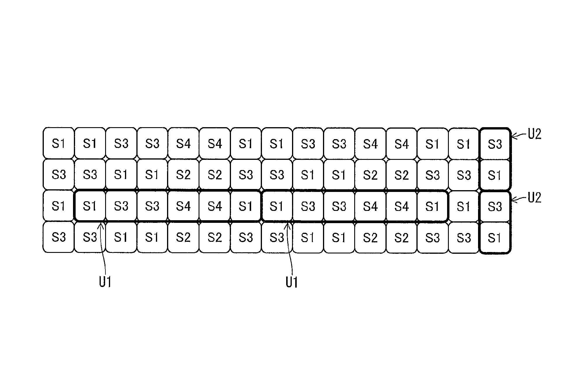
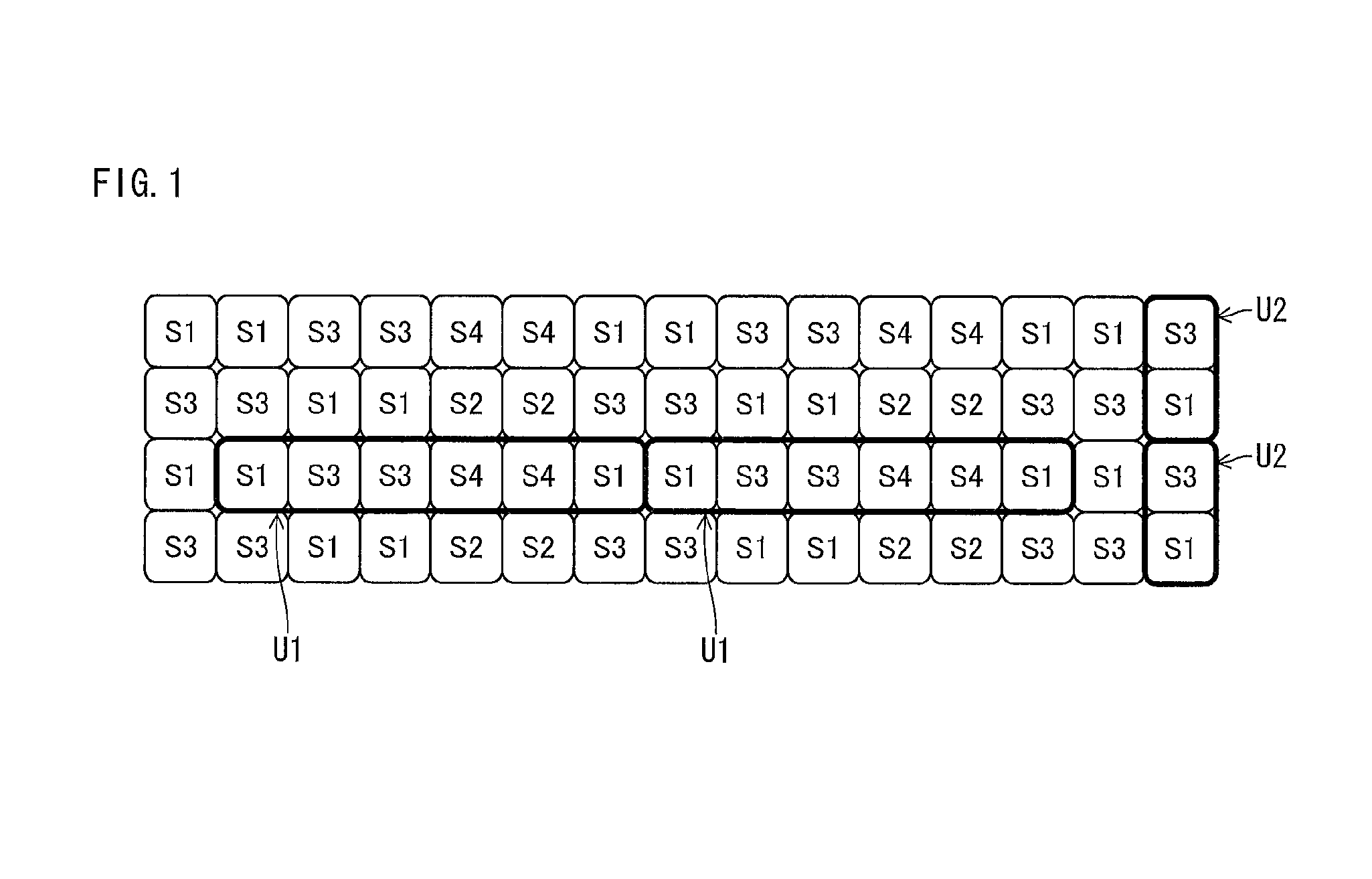
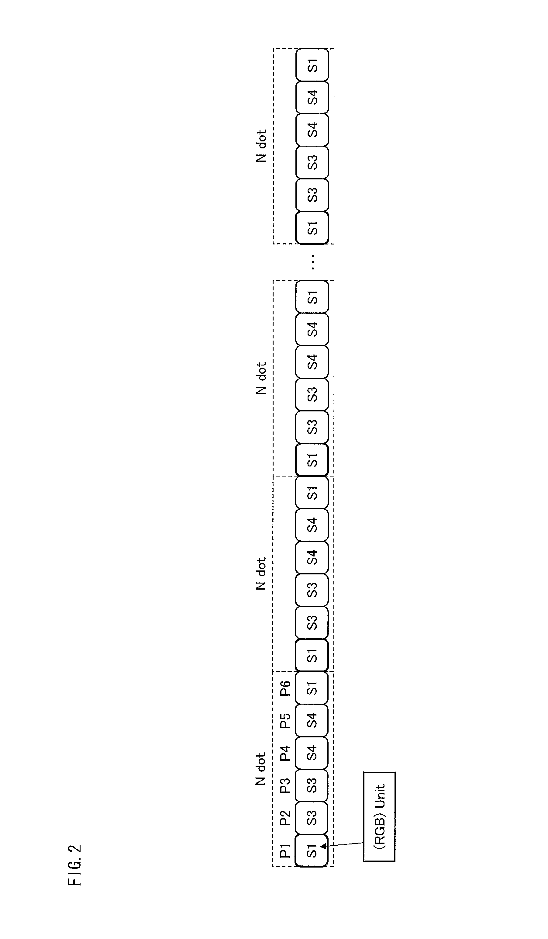
[0076]The present embodiment includes pixels each changing its luminance in one of a plurality of different sequences, for example, the following four types of sequence: (i) bright->bright->dark->dark (sequence S1), (ii) bright->dark->dark->bright (sequence S2), (iii) dark->dark->bright->bright (sequence S3), and (iv) dark->bright->bright->dark (sequence S4), to include at least one pixel for e...


PUM

PropertyMeasurementUnit
write frequencyaaaaaaaaaa
frequencyaaaaaaaaaa
driving frequencyaaaaaaaaaa

Abstract

The present invention provides a display device which is arranged so that when an image is scrolled, a noise pattern does not easily overlap the image. The display device includes a display region that includes a region in which an arrangement pattern (U1) including X i-th pixels arranged next to one another in the row direction for each data color, the arrangement pattern being repeated in the row direction, the X being represented byX=A / 2+A·Q, where Q is an integer of 0 or greater, and is defined for each row.

Description

REFERENCE TO RELATED APPLICATIONS[0001]This application is a national stage application under 35 USC 371 of International Application No. PCT / JP2010 / 062803, filed Jul. 29, 2010, which claims priority from Japanese Patent Application No. 2009-270817, filed Nov. 27, 2009, the entire contents of which are incorporated herein by reference.FIELD OF THE INVENTION[0002]The present invention relates to a display device that displays a halftone with use of a temporal luminance change.BACKGROUND OF THE INVENTION[0003]There has been proposed a technique for improving the viewing angle characteristic of a liquid crystal display device by displaying an input tone a plurality of times while switching the γ characteristic. Patent Literature 1, for example, discloses an arrangement of (i) dividing pixels in a predetermined pixel unit into high-luminance pixels and low-luminance pixels and (ii) changing the brightness for each frame.[0004]FIG. 40 illustrates a brightness setting method disclosed in ...

Claims


Application Information

Patent Timeline
Patent Type & Authority Patents(United States)
IPC IPC(8): G09G3/36G02F1/13G09G3/20
CPCG09G3/3648G09G3/2025G09G2320/0276G09G2320/0261G09G2320/0673
Inventor IRIE, KENTAROHKAWABATA, MASAESHIMOSHIKIRYOH, FUMIKAZU
Owner SHARP KK
Why Eureka
Try Eureka