
Structural assembly with a flexed, tied panel

a technology of structural assembly and flexural deformation, which is applied in the direction of building components, curtain accessories, advertising, etc., can solve the problems of corrugated repose and reduction of any tension in the plane element, and achieve the effect of high restitution coefficien

Inactive Publication Date: 2014-09-16
CONTRA VISION
View PDF52 Cites 16 Cited by
  • Summary
  • Abstract
  • Description
  • Claims
  • Application Information

AI Technical Summary

Problems solved by technology

However, in the case of corrugated paper or card, the corrugated element is typically deformed in a material state and under conditions such that, were it not attached to the one or more planar sheets, it would still be corrugated in repose.
The curved and plane components are connected by means of folded card tabs, which will inevitably open up in use and cause reduction of any tension in the plane element.

Method used


Image

  • Structural assembly with a flexed, tied panel
  • Structural assembly with a flexed, tied panel
  • Structural assembly with a flexed, tied panel

Examples


Embodiment Construction

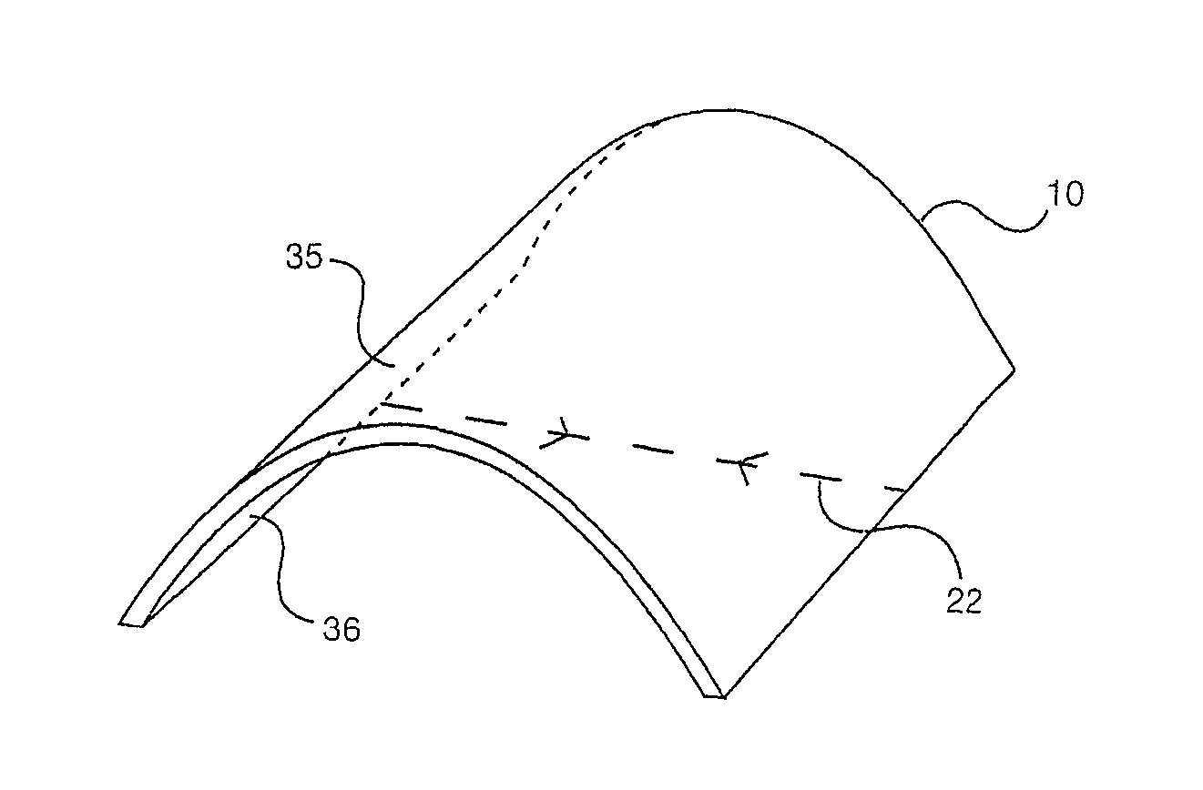
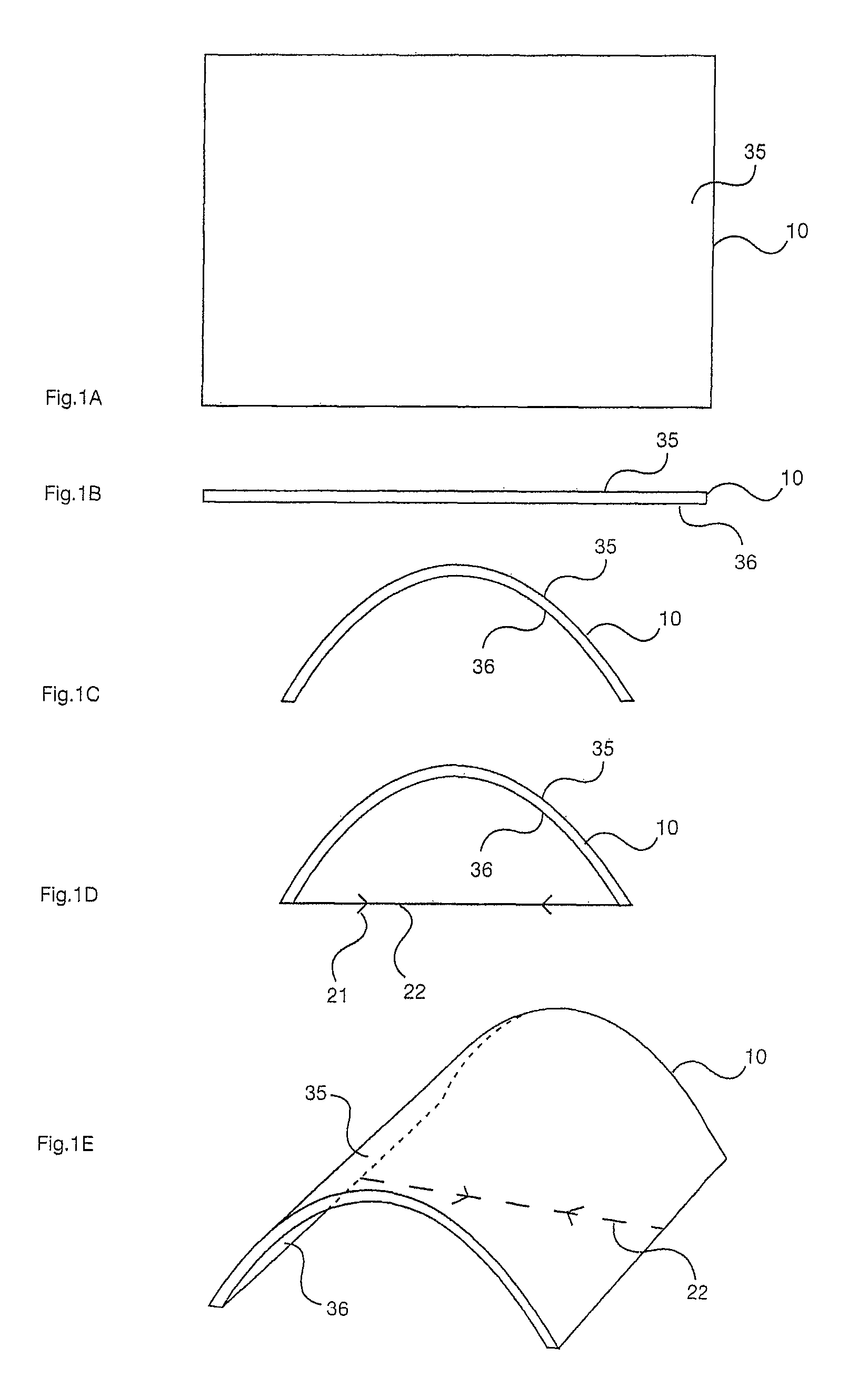
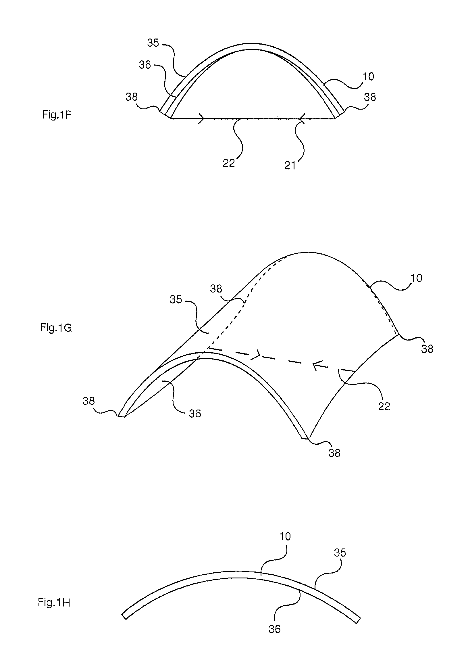
[0326]FIGS. 1A-G illustrate panel 10, tied by a single tie rod 22. Panel 10 is shown on plan in FIG. 1A and in edge elevation in FIG. 1B before flexure, illustrated in FIG. 1C. FIG. 1D illustrates single linear tie rod 22, for example a rod or cable (the arrow heads 21 indicating tensile force) and a diagrammatic perspective of the resultant temporary assembly is illustrated in FIG. 1E. FIG. 1F illustrates the secondary deflection of the corners of the panel 38 in elevation, which is also shown in perspective in FIG. 1G. Such an assembly may also be used temporarily to create an “intermediate panel geometry” before attaching a membrane tie and any linear connector or connectors, or a tubular membrane tie. If a membrane tie is used, in the final “flexurally deformed geometry”, this secondary deflection or out-of-alignment is eliminated. If the linear tie is released after a substantial elapsed time, the flexed panel will not revert to its initial geometry but have a residual panel ge...


PUM


Abstract

An assembly includes a flexurally deformed panel, which is connected to a membrane tie by a linear connector and is tied by the membrane tie to form a geometrically stable pre-stressed structure. More than one panel may be flexurally deformed and tied together in an assembly and more than one membrane tie may be present within an assembly. Panels are typically semi-rigid sheet materials, for example metal sheets, plastic sheets, or sheets of composite materials, such as glass or carbon fiber reinforced plastics or resins. Membrane tie members are typically flexible, for example plastic films, fabrics or nets or arrays of rods or cables. The assemblies have many different geometric forms and many different practical applications. Assemblies may be relatively large, for example demountable and reusable shelters or flat-pack point-of-purchase display assemblies, or may be relatively small, for example a photograph or postcard display system.

Description

CROSS-REFERENCE TO RELATED APPLICATIONS[0001]This application is the U.S. National Phase of PCT / IB2007 / 003620, filed Aug. 21, 2007, which in turn claims the benefit of PCT / IB2006 / 003667, filed Aug. 21, 2006, and U.S. Provisional Patent Application Ser. No. 60 / 831,306, titled “STRUCTURAL ASSEMBLY WITH A FLEXED, TIED PANEL” filed Feb. 23, 2007, the entire contents of all of which are incorporated by reference herein.BACKGROUND[0002]1. Field of the Invention[0003]Embodiments of the present invention relate to structural systems or structures comprising a flexurally deformed panel.[0004]2. Description of Related Art[0005]Structural systems involving more than one panel connected together are commonplace, for example folded plate roofs, boxes, etc. Connecting two originally planar elements together, one of which is substantially deformed, is also known. For example, corrugated paper or card comprises a sheet of plane paper or card which is deformed by means of pressure, heat and water co...

Claims


Application Information

Patent Timeline
Patent Type & Authority Patents(United States)
IPC IPC(8): G09F15/00G09F17/00G09F1/06G09F1/10G09F15/02G09F19/22
CPCG09F1/06G09F7/18G09F19/22G09F15/0062G09F15/02G09F1/065G09F15/0068G09F15/0025G09F15/0043G09F1/10G09F15/0075A47G1/14G09F2015/0093
Inventor HILL, G., ROLAND
Owner CONTRA VISION
Learn More