Control panel comprising resistive keys and spacers

a technology of resistive keys and control panels, applied in the field of control panels, can solve problems such as loss of pressure or pre-load on the spacer, and achieve the effects of simple, effective and economical solution

Active Publication Date: 2014-09-16
APTIV TECH LTD
View PDF9 Cites 0 Cited by
  • Summary
  • Abstract
  • Description
  • Claims
  • Application Information

AI Technical Summary

Benefits of technology

[0008]The present invention is intended to remedy the disadvantages mentioned above by proposing a simple, effective, and economical solution.
[0009]To this end, the invention proposes a control panel, particularly for a motor vehicle, including a cover which is mounted on a support and which is provided with at least one tactile pressing detection zone forming a control button, in which a force sensor having a pressure-sensitive zone is arranged between the cover and the support, behind the detection zone, so as to detect the actuation of the control button to produce an electrical control signal when a user applies a determined tactile pressing force to the detection zone, the tactile pressing force being transmitted axially towards the sensitive zone via a spacer made of elastically compressible material that is interposed between the sensor and the cover, the spacer being mounted axially compressed between the sensor and the cover in the absence of tactile pressing on the detection zone so that the sensor is subject to a prestressing force at rest, characterized by the fact that the spacer includes at least one compressible portion provided with a transversal top surface which bears against the cover and with a transversal bottom surface which bears against the sensitive zone of the sensor, the top surface having an area smaller than the area of the bottom surface so as to minimize the reaction force applied by the spacer to the cover while ensuring even distribution of the prestressing force and of the tactile pressing force over the sensitive zone of the sensor.
[0010]By means of the invention, the contact surface between the spacer and the cover is minimized which allows reduction of the stresses applied to the cover. The invention permits application of a prestressing force to the sensor which is less than the prestressing force applied to the sensor by a conventional spacer in the form of a parallelepipedal slab of uniform axial thickness, while guaranteeing that there is always a minimum prestressing force despite manufacturing and assembly tolerances and despite temperature variations.
[0011]By minimizing the intensity of the nominal prestressing force, the invention permits reduction of risks of creep due to too great pressing forces at the sensor and at the cover. Moreover, the smaller the prestressing force, the easier will be the detection of the activation of the associated control button.

Problems solved by technology

However, the mounting or arranging of the spacer to be in compression between the sensor and the cover tends to cause an outward deformation of the cover at the level of the spacer that detracts from the external appearance of the cover.
These disadvantages are particularly problematic in applications subject to large temperature variations, as in a motor vehicle, which can lead to a loss of pressure or pre-load on the spacer.

Method used


Image

  • Control panel comprising resistive keys and spacers
  • Control panel comprising resistive keys and spacers
  • Control panel comprising resistive keys and spacers

Examples


first embodiment

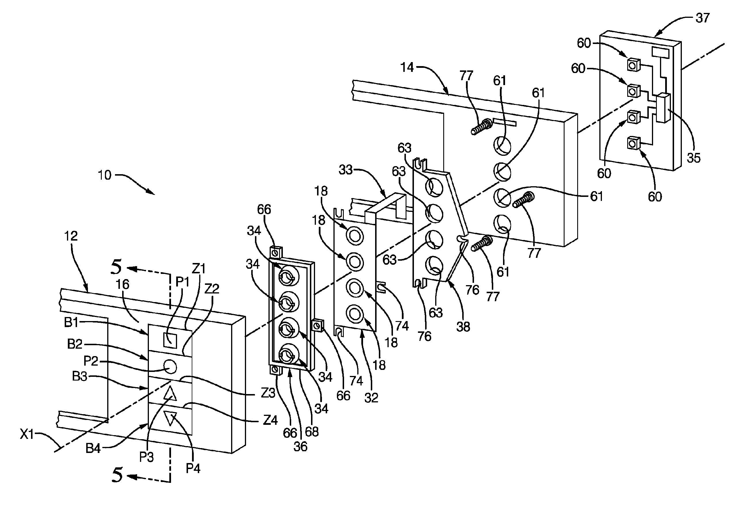
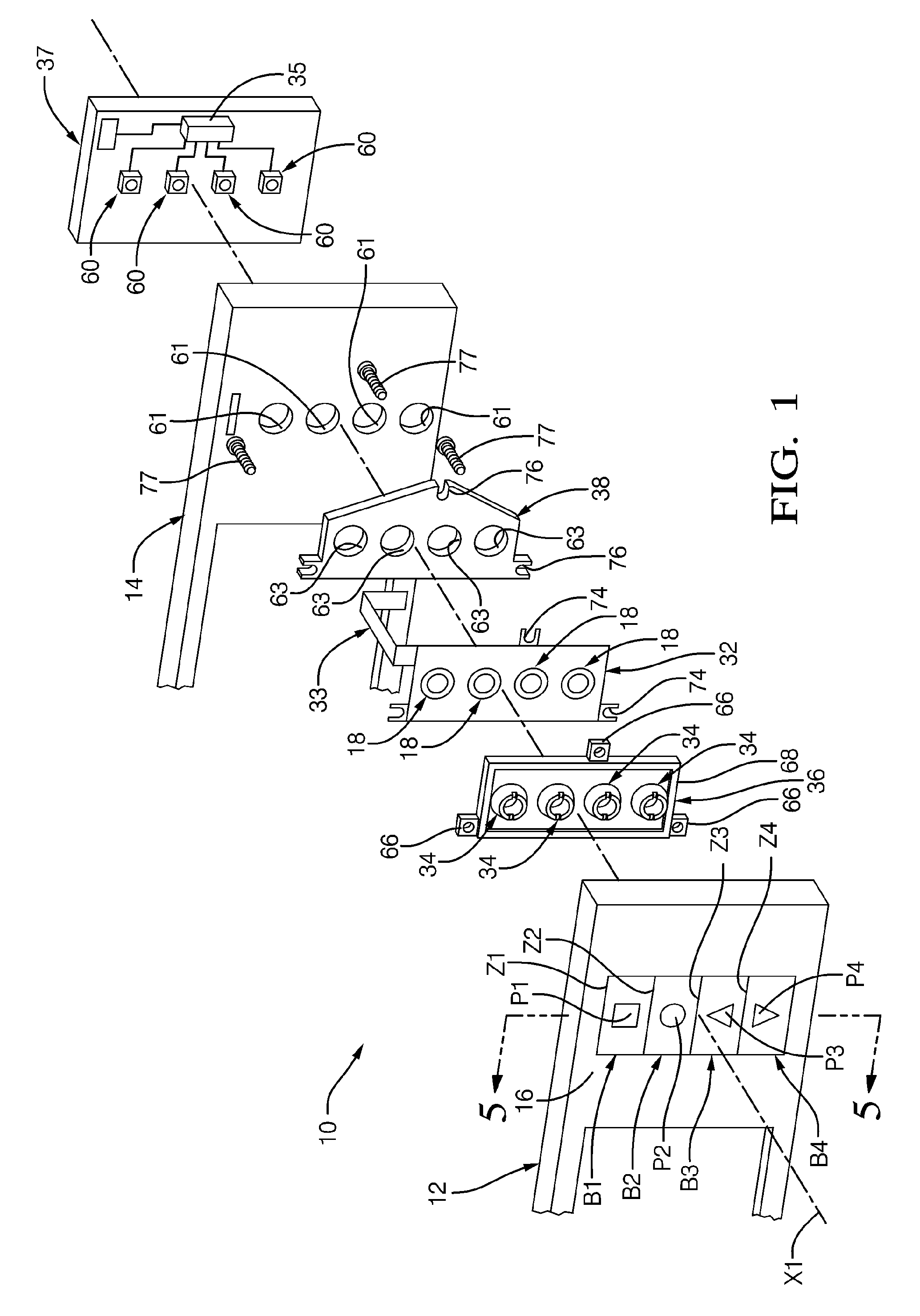
[0025]FIG. 1 shows a control panel 10 for a motor vehicle dashboard, made in accordance with a first embodiment in accordance with the teachings of the invention. It here includes a cover 12 which is mounted on a support 14, the outer surface 16 of the cover 12 including a plurality of tactile pressing detection zones Z1, Z2, Z3, Z4 forming a plurality of control buttons B1, B2, B3, B4, or resistive keys. In accordance with the example shown here, the resistive keys are four in number. Preferably, each control button B1, B2, B3, B4 is provided with a pictogram P1, P2, P3, P4 designed to be back-lit. The pictograms P1, P2, P3, P4 are created for example by laser scraping on the outer face 16 of the cover 12 and thus form back-lighting zones.

[0026]In the remainder of the description by way of non-limiting example an axial orientation will be used along an axis X1 substantially at right-angles to the general plane of the cover 12, orientated from the front towards the rear, i.e. from t...

second embodiment

[0051]Within the framework of the second embodiment shown in FIGS. 4 to 6, each spacer 34 includes a plurality of compressible portions 40, 42. These compressible portions 40, 42 are here each in the form of a truncated pyramid elongated parallel with the plane of the cover 12. More precisely, each compressible portion 40, 42 here has two substantially trapezoidal lateral faces 46 and two substantially trapezoidal end faces 48 which meet at the top to form the top surface 44 which is substantially rectangular and designed to bear against the cover 12.

[0052]Advantageously, the compressible portions 40, 42 are distributed substantially parallel with the outer peripheral edge of the associated sensitive zone 30 of the sensor 18. Here, each sensitive zone 30 generally has a rectangular outer contour and the spacer 34 includes, opposite the sensitive zone 30, two longitudinal compressible portions 40 which extend in the length of the sensitive zone 30 and two transversal compressible por...


PUM

PropertyMeasurementUnit
prestressing forceaaaaaaaaaa
areaaaaaaaaaaa
compressibleaaaaaaaaaa

Abstract

Control panel including a cover mounted on a support that is provided with a tactile pressing detection zone in which a force sensor that includes a pressure-sensitive zone is arranged behind a detection zone between the cover and the support so as to produce an electrical control signal when a user applies a determined tactile pressing force to the detection zone. The tactile pressing force is transmitted axially (X1) towards the sensitive zone via a spacer made of elastically compressible material interposed between the sensor and the cover. The spacer includes at least one compressible portion that defines a transversal top surface that bears against the cover and a transversal bottom surface that bears against the sensitive zone of the sensor. The top surface has an area smaller than the area of the bottom surface.

Description

CROSS-REFERENCE TO RELATED APPLICATION[0001]This application claims the benefit under 35 U.S.C. §371 of published PCT Patent Application Number PCT / EP 2012 / 054214, filed Mar. 12, 2012 and claims priority to French Patent Application 1152302 filed Mar. 21, 2011, and published as WO2012 / 126754 Sep. 27, 2012, the entire contents of which is hereby incorporated by reference herein.TECHNICAL FIELD OF INVENTION[0002]The present invention relates to a control panel, particularly for a motor vehicle, including resistive keys.BACKGROUND OF INVENTION[0003]The present invention relates more particularly to a control panel intended to be arranged in the passenger space of a motor vehicle, particularly on the dashboard, and which includes at least one control button in the form of a resistive key designed to control a determined function, for example to control the starting or stopping of the air-conditioning function.[0004]The control panel includes a cover that is mounted on a support and whic...

Claims


Application Information

Patent Timeline
Patent Type & Authority Patents(United States)
IPC IPC(8): G01L1/04G01L1/20G01L1/22H03K17/96
CPCG01L1/2287H03K17/9625G01L1/205
Inventor AUBERGER, STEPHANELOBSTEIN, ROLAND
Owner APTIV TECH LTD
Why Eureka
Try Eureka