Aircraft turbine engine with planetary or epicyclic gear train

a technology of planetary or epicyclic gear train and turbine engine, which is applied in the direction of engine starters, machines/engines, efficient propulsion technologies, etc., can solve the problems of mechanical offtake, add to the impact of mechanical offtake, and reduce the operability of hp compressors, so as to achieve simple, effective and economical solution, and the effect of starting the engin

Active Publication Date: 2021-06-29
SN DETUDE & DE CONSTR DE MOTEURS DAVIATION S N E C M A
View PDF17 Cites 0 Cited by
  • Summary
  • Abstract
  • Description
  • Claims
  • Application Information

AI Technical Summary

Benefits of technology

[0014]The present invention proposes a simple, effective and economical solution to this problem by virtue of an arrangement of the turbine engine comprising a reduction gear that makes it possible to start said engine more easily by driving the LP spool.
[0016]Thus, the fan can be decoupled from the LP spool, for example during start-up of the turbine engine. This makes it possible to prevent the disadvantages described above. Positioning the disengageable or decoupling means in the region of the connection between the stator casing and an element that is intended to be fixed when the turbine engine is in operation facilitates the implementation of said means.
[0018]Start-up of the turbine engine is thus initiated by means of the LP spool. Start-up does not take place at the HP spool, which makes it possible to eliminate the radial shaft connected to the HP spool from the prior art (or rather to move said shaft in order for it to cooperate instead with the LP spool). Eliminating said shaft makes it possible to simplify the HP spool which does not comprise any mechanism for connection to the radial shaft, and to thus provide for a reduction in the size of said spool, in particular the radial dimension thereof. The HP spool does not need to be provided with an electric motor for start-up either, which motor tends to place excessive stress on the HP spool. The HP spool can thus be used solely for the supply for the combustion chamber, and for generating combustion gases. It is thus possible to have access to a twin-spool turbine engine, the HP spool of which is of a reduced size, which promotes optimisation of the bypass ratio of said engine.

Problems solved by technology

However, said mechanical offtake is disadvantageous for the operability of the HP compressor.
Increasing the BPR therefore has a negative impact on the operability of the HP spool, which thus adds to the impact of the mechanical offtake.
The same problem emerges when the overall pressure ratio (OPR) is increased, which is a trend that is also seen in recent turbine engines of which the thermal efficiency is to be increased.
Now, configurations without air offtake are sometimes studied in order to achieve an engine having a reduced fuel consumption, which reduces the air flow rate of the HP compressor and thus has a negative impact on the operability thereof.
Moreover, in this latter type of configuration, the function of supplying the aircraft with compressed air can be undertaken by electrical equipment, which thus further increases the need for mechanical offtake from the turbine engine.
The increase in the power required by the aircraft, the increase in the BPR leading to a reduction in the size of the spools, and the reduction in the air offtakes contribute to making it more and more difficult to achieve the current situation, in which the mechanical offtake occurs on the HP spool.
This configuration makes it possible to eliminate the problem of the operability of the HP spool, but produces another problem.
Specifically, if the device for removing power now meshes with the LP shaft, it is no longer possible to start the turbine engine by driving the HP spool.
However, this solution would have a significant impact on the mass and the complexity of the turbine engine, which is reason to attempt to keep just one device for removing power that meshes with the LP shaft.
It therefore appears that very high energy and power are required for ensuring start-up, which is disadvantageous in particular on account of the dimensioning of the auxiliary power unit (APU) that is to be reviewed, and possibly that of the electric or pneumatic power circuit that is to be increased.
Moreover, this would mean that the engine would have significant thrust upon start-up on account of the fan being driven, which could result in safety problems in the vicinity of the aircraft before takeoff.

Method used


Image

  • Aircraft turbine engine with planetary or epicyclic gear train
  • Aircraft turbine engine with planetary or epicyclic gear train
  • Aircraft turbine engine with planetary or epicyclic gear train

Examples


Embodiment Construction

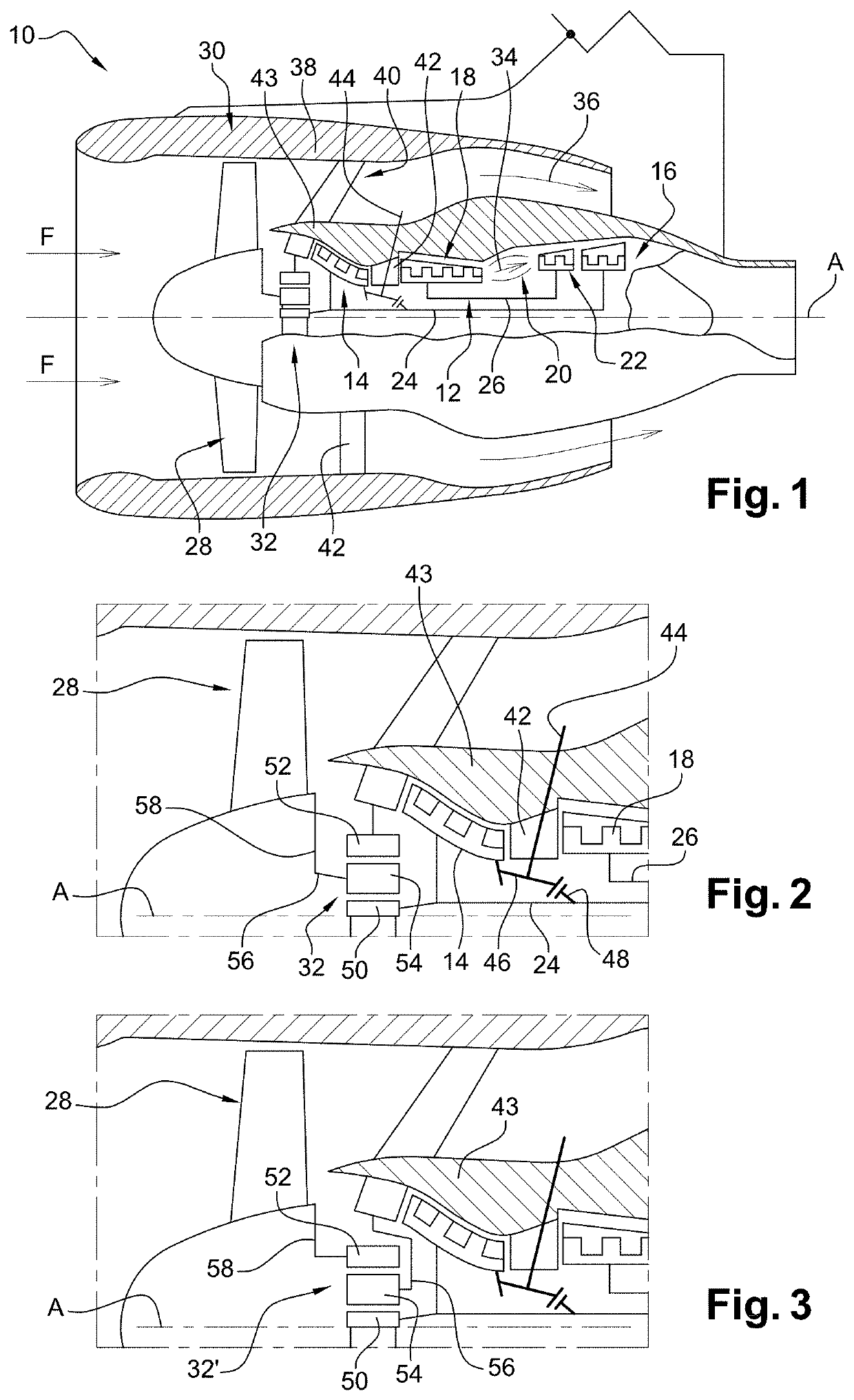
[0045]Reference is first made to FIGS. 1 and 2, which schematically show a double-spool bypass aircraft turbine engine 10.

[0046]The turbine engine 10 comprises, in a conventional manner, a gas generator 12, on either side of which a low-pressure compressor 14 and a low-pressure turbine 16 are arranged, said gas generator 12 comprising a high-pressure compressor 18, a combustion chamber 20 and a high-pressure turbine 22. In the following, the terms “upstream” and “downstream” are regarded in a main direction F of flow of the gases in the turbine engine, said direction F being in parallel with the longitudinal axis A of the turbine engine.

[0047]The rotors of the low-pressure compressor 14 and of the low-pressure turbine 16 form a low-pressure or LP spool and are interconnected by a low-pressure or LP shaft 24 that is centred on the axis A. Similarly, the rotors of the high-pressure compressor 18 and of the high-pressure turbine 22 form a high-pressure or HP spool and are interconnecte...


PUM


Abstract

Aircraft turbine engine comprising a low-pressure spool that comprises a low-pressure shaft (24), means (44) for taking off power from said low-pressure shaft, and a fan (28) that is driven by said low-pressure shaft by means of a reduction gear (32), said reduction gear comprising at least one first element (50) that is connected to said low-pressure shaft for conjoint rotation, at least one second element (56) that is connected to said fan for conjoint rotation, and at least one third element (52) that is connected to a stator casing of the turbine engine, characterised in that said at least one third element is connected to said stator casing by disengageable connection means (60), and comprising at least one member that can move from a first position in which said at least one third element is fixedly connected to said stator casing into a second position in which said at least one third element is separated from said stator casing and is free to rotate about said longitudinal axis.

Description

TECHNICAL FIELD[0001]The present invention relates to an aircraft turbine engine comprising a planetary or epicyclic reduction gear.PRIOR ART[0002]An aircraft turbine engine typically comprises a low-pressure (LP) spool comprising a low-pressure (LP) shaft, and a high-pressure (HP) spool comprising a high-pressure (HP) shaft. The low-pressure and high-pressure shafts extend along the same longitudinal axis of the turbine engine.[0003]The turbine engine further comprises a fan that is driven by the low-pressure shaft by means of a planetary or epicyclic reduction gear, as described in FR-A1-2 817 912.[0004]The turbine engine provides the propulsive power but also the power required by all the systems of the aircraft. There is a tendency to increase said power that is removed from the turbine engine, inter alia in order to increase the comfort for the passengers of the aircraft.[0005]This power is almost always removed from the HP spool. This is generally achieved by means of a radial...

Claims


Application Information

Patent Timeline
Patent Type & Authority Patents(United States)
IPC IPC(8): F01D15/12F01D19/00F02K3/06F02C7/36F02C7/275F02C7/277
CPCF01D15/12F01D19/00F02C7/275F02C7/277F02C7/36F02K3/06F05D2260/402F05D2260/4023F05D2260/40311F05D2260/85Y02T50/60F16D25/0635
Inventor BORDONI, NILSKUBIAK, GUILLAUME PATRICELEMARCHAND, KEVIN MORGANE
Owner SN DETUDE & DE CONSTR DE MOTEURS DAVIATION S N E C M A
Why Eureka
Try Eureka