Installation element of an installed packing

a technology of installation element and installed packing, which is applied in the direction of clothing, lighting and heating apparatus, and coolers, etc., can solve the problems that the elasticity surrounding the hole can practically no longer be realized, and achieve the effects of convenient manufacture, good longevity, and economical manufacturability

Active Publication Date: 2014-09-16
GEA 2H WATER TECH GMBH
View PDF40 Cites 49 Cited by
  • Summary
  • Abstract
  • Description
  • Claims
  • Application Information

AI Technical Summary

Benefits of technology

[0005]Therefore, the present invention is based on the object of creating an installation element of the type named above that can easily be locked with further, perhaps identical plate elements with a low application of force, such that once created, a locking connection is to be long-lasting.

Problems solved by technology

If, however, a thicker material is selected for the plate element, such an elasticity surrounding a hole can practically no longer be realized.

Method used


Image

  • Installation element of an installed packing
  • Installation element of an installed packing
  • Installation element of an installed packing

Examples


Embodiment Construction

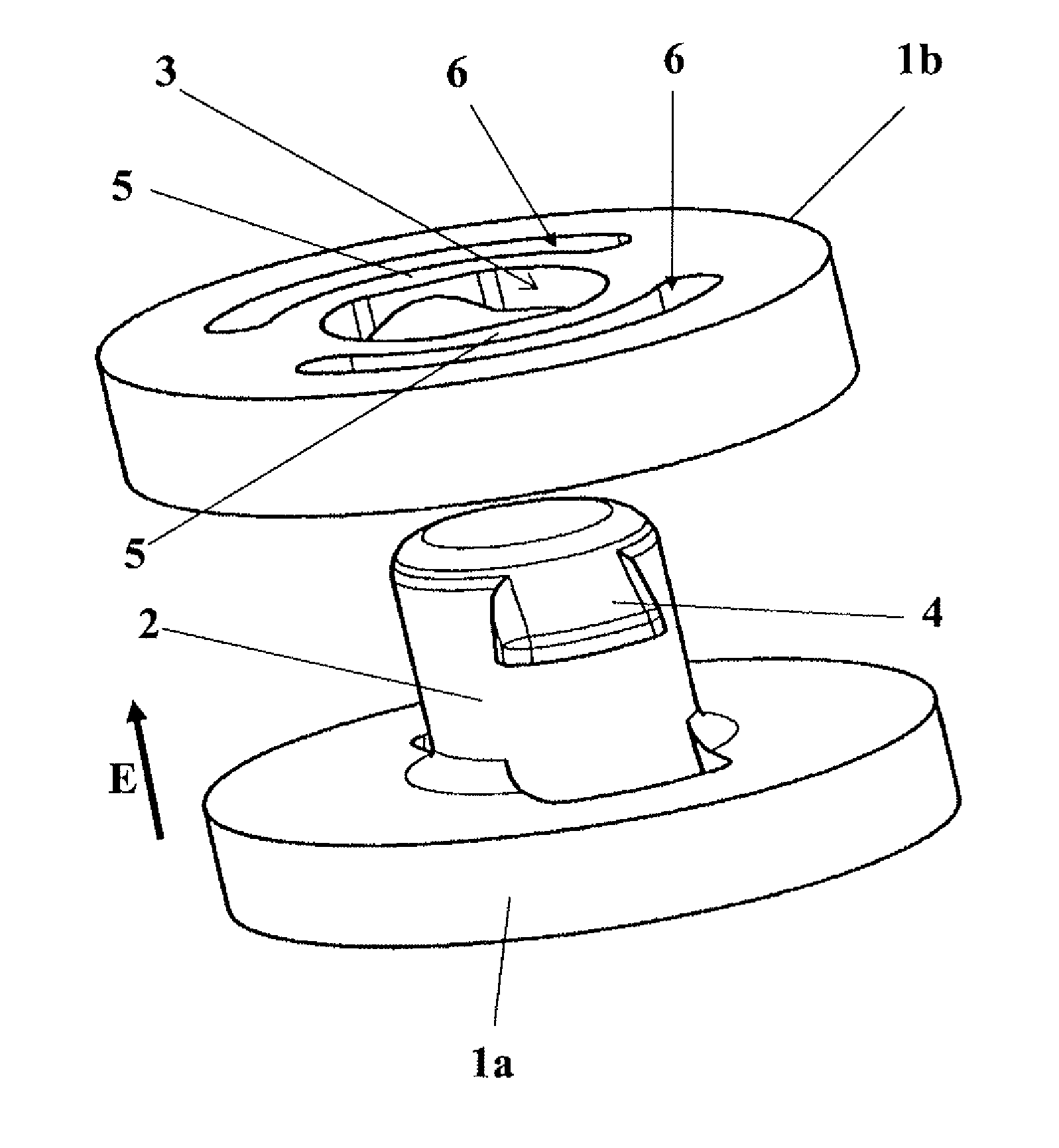
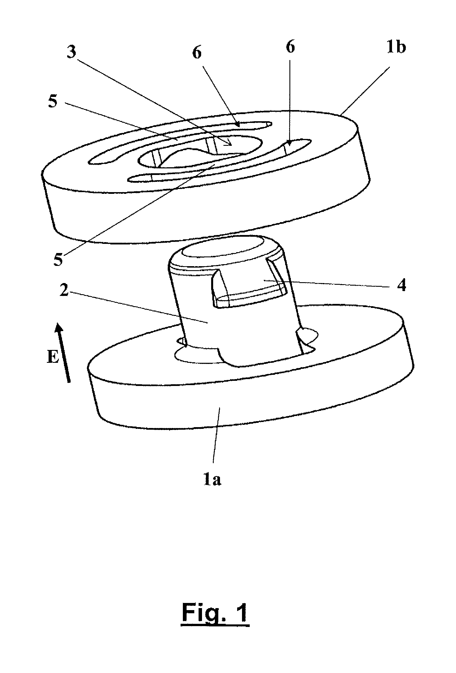
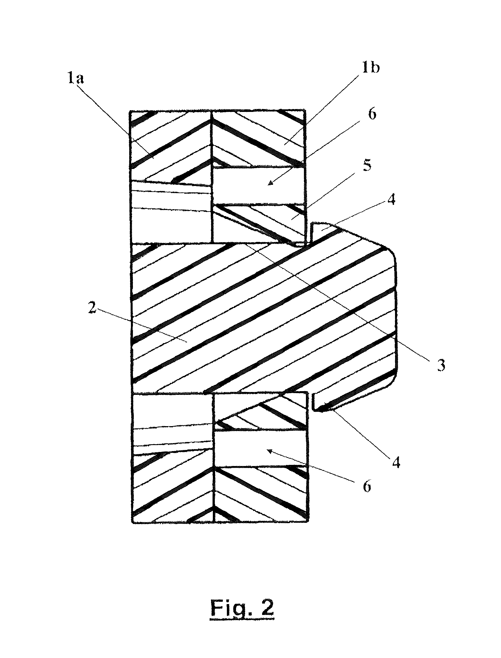
[0029]Installation elements 1 (FIGS. 4 and 5), which are preferably made of a plastic suitable for this purpose, are locked to one another by pegs 2 and corresponding recesses 3, in order for example to form an installed packing for a cooling tower. Such installation elements 1, for example in the form of a grid mat, are known from the prior art cited above. Pegs 2 can either be fashioned in one piece with installation element 1 during the manufacture thereof (such as by simultaneous molding) or can subsequently be glued or welded with a foot element onto the installation element. The recesses similarly may be formed integrally and simultaneously with the installation element 1 during the manufacturing process, or may be formed in separate pieces that are glued or welded onto the installation element.

[0030]FIG. 1 of the drawing shows, in a perspective view, a peg 2 of an installation element 1a (shown only partially) that is introduced, in a direction of introduction indicated by ar...


PUM


Abstract

An installation element of an installed packing for material and / or heat exchange between gases and liquids, having pegs and recesses for engaging with at least one further installation element. In order to make the engagement easier the recesses each are associated with ring gap segments.

Description

RELATED APPLICATIONS[0001]This application is a continuation-in-part of PCT / EP2009 / 000361 filed Jan. 22, 2009 and designating the United States.BACKGROUND OF THE INVENTION[0002]The present invention relates to an installation element of an installed packing for the exchange of material and / or heat between gases and liquids, having pegs and recesses for locking with at least one additional identical installation element.[0003]Such installation elements are known from, inter alia, DE 197 33 480 C2, and, in the state in which they are connected to additional identical installation elements, act as what is known as an installed packing that is situated for example in a wet cooling tower in order on the one hand to cause warm water that is to be cooled to flow from above to below through the installed packing, and on the other hand to conduct cooling air through the installed packing in a cross-current and / or counter-current. Here, each installation element is made up of a plate-shaped b...

Claims


Application Information

Patent Timeline
Patent Type & Authority Patents(United States)
IPC IPC(8): F16B9/00B01J19/32F28F25/08
CPCF28F25/08B01J19/32F28F2275/143B01J2219/32483F28F2275/085B01J2219/32251B01J2219/3313Y10T24/45775Y10T403/4662F16B2200/20
Inventor WOICKE, NINA
Owner GEA 2H WATER TECH GMBH
Why Eureka
Try Eureka