
Non-isolated resonant converter

a resonant converter and non-isolation technology, applied in the direction of electric variable regulation, process and machine control, instruments, etc., to achieve the effect of reducing the size of the auto-transformer, and reducing the resistance loss of the winding

Active Publication Date: 2014-09-16
SPI ELECTRONICS +1
View PDF5 Cites 42 Cited by
  • Summary
  • Abstract
  • Description
  • Claims
  • Application Information

AI Technical Summary

Benefits of technology

The patent text describes a non-isolated resonant converter that uses an auto-transformer with a small size and low loss to replace the isolated transformer. This reduces the loss of the resonant converter and increases its power density. The technical effect of this invention is the development of a more efficient and power-dense resonant converter.

Problems solved by technology

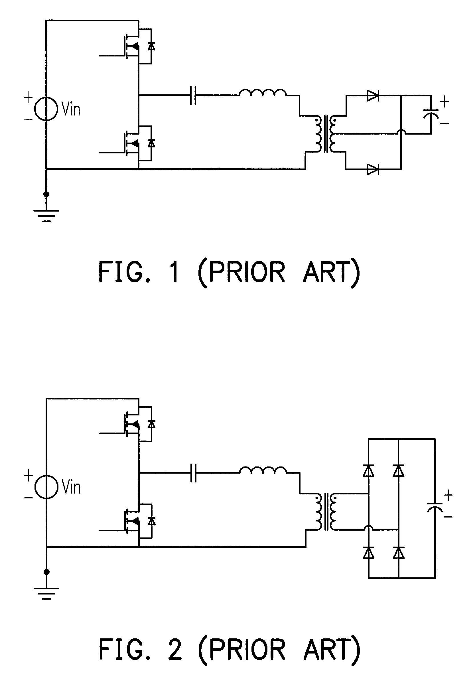
Furthermore, the characteristic of using one winding of the auto-transformer makes that the auto-transformer has distinctive to the isolated transformer and cannot be replaced by the isolated transformer directly to form the resonant converter in real applications.

Method used


Image

  • Non-isolated resonant converter
  • Non-isolated resonant converter
  • Non-isolated resonant converter

Examples


Embodiment Construction

[0043]The exemplary embodiments of the disclosure are illustrated in detail below with reference to the accompanying drawings. In addition, components / members of the same reference numerals are used to represent the same or similar parts in the accompanying drawings and implementations wherever it is possible.

[0044]The structures and performances of the present invention will be described in detail with reference to the accompanying drawings.

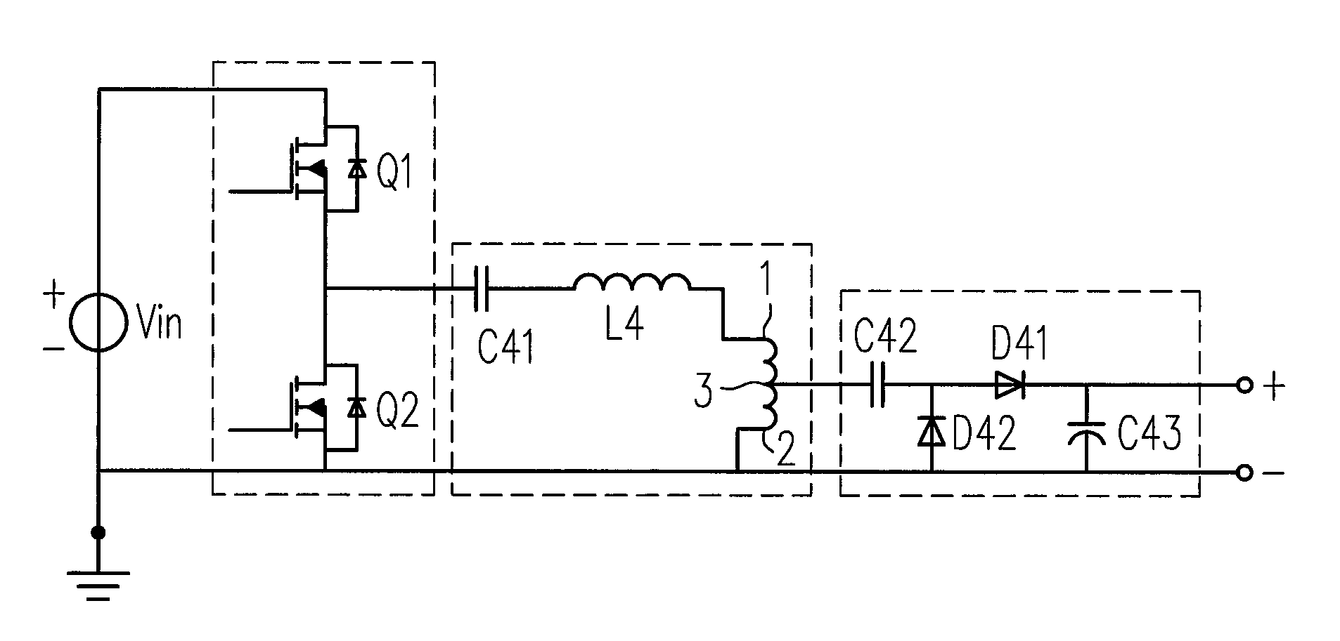
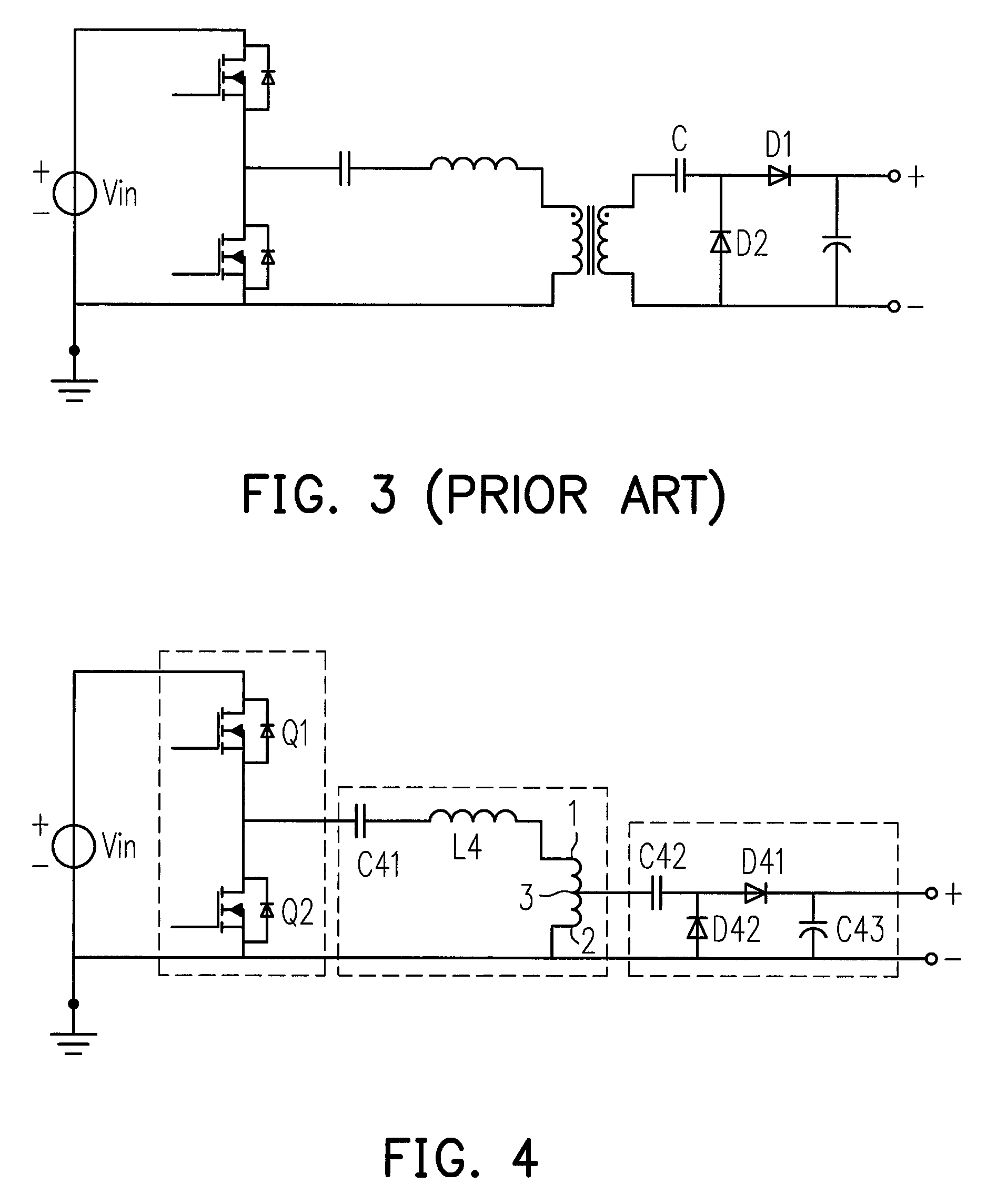
[0045]Referring to FIG. 21, the present invention provides a non-isolated resonant converter. The non-isolated resonant converter mainly includes three parts: a switch circuit, a resonant circuit and a rectifying-filtering circuit. The switch circuit, the resonant circuit and the rectifying-filtering circuit are sequentially connected. The resonant circuit includes an auto-transformer, a capacitor and an inductor, wherein the capacitor and the inductor are connected to the auto-transformer. It should be noted that the capacitor and the inductor ...


PUM


Abstract

A non-isolated resonant converter is provided. The provided non-isolated resonant converter includes a switch circuit, a resonant circuit and a rectifying-filtering circuit. The switch circuit, the resonant circuit and the rectifying-filtering circuit are sequentially connected. The resonant circuit includes an auto-transformer, a capacitor and an inductor, wherein the capacitor and the inductor are connected to the auto-transformer. The configuration of the provided non-isolated resonant converter has small size, low loss and high power density.

Description

CROSS-REFERENCE TO RELATED APPLICATION[0001]This application claims the priority benefit of China application serial no. 201110120398.9, filed on May 11, 2011. The entirety of the above-mentioned patent application is hereby incorporated by reference herein and made a part of this specification.BACKGROUND OF THE INVENTION[0002]1. Field of the Invention[0003]The present invention generally relates to a power conversion field, in particular, to a non-isolated resonant converter applied to photovoltaic inverters, LED constant-current driving and multi-path LED constant-current driving.[0004]2. Description of Related Art[0005]High frequency, high efficiency and high power density are the developing trends of switching power supply. By the characteristics of soft switching and great EMI performance, the resonant converter becomes important research issues in the power conversion technology field.[0006]Most of the common resonant converter is formed based on the isolated transformer. Refe...

Claims


Application Information

Patent Timeline
Patent Type & Authority Patents(United States)
IPC IPC(8): H05B37/02H02M1/00H02M3/158H02M3/335
CPCH02M3/158H02M3/33569H02M2001/0058Y02B70/1433Y02B70/1425Y02B70/1491Y02B70/10H02M1/0058H02M3/01
Inventor XU, MINGLI, XINLEI
Owner SPI ELECTRONICS
Learn More