Belt driving apparatus and image forming apparatus

a driving apparatus and belt technology, applied in the direction of electrographic process apparatus, instruments, optics, etc., can solve the problems of affecting the stability the lateral deviation of the belt member, and the liable instability of the frictional force of the contact belt, so as to improve the responsiveness to lateral deviation (movement) of the belt member and enhance the contact stability

Inactive Publication Date: 2014-09-16
CANON KK
View PDF25 Cites 12 Cited by
  • Summary
  • Abstract
  • Description
  • Claims
  • Application Information

AI Technical Summary

Benefits of technology

[0008]A principal object of the present invention is to provide a belt driving apparatus capable of improving responsiveness to lateral deviation (movement) of a belt member by enhancing contact stability between a belt member free end and a frictional portion.

Problems solved by technology

It has been generally known that such a belt member stretched by the plurality of stretching rollers is accompanied with a problem that the belt member is laterally moved in either one of roller end portions depending on roller outer diameter accuracy or alignment accuracy among the rollers.
This problem is not limited to the intermediary transfer belt but also occurs in the belt driving apparatus for stretching the belt by the plurality of stretching members to drive the belt.
However, the end portion of the belt member contacted to the frictional portion is a free end and therefore the contact belt the belt member end portion and the frictional force is liable to become unstable depending on a shape of the belt member end portion.

Method used


Image

  • Belt driving apparatus and image forming apparatus
  • Belt driving apparatus and image forming apparatus
  • Belt driving apparatus and image forming apparatus

Examples


embodiment 1

(Embodiment 1)

[0025]An image forming apparatus in this embodiment of the present invention will be described.

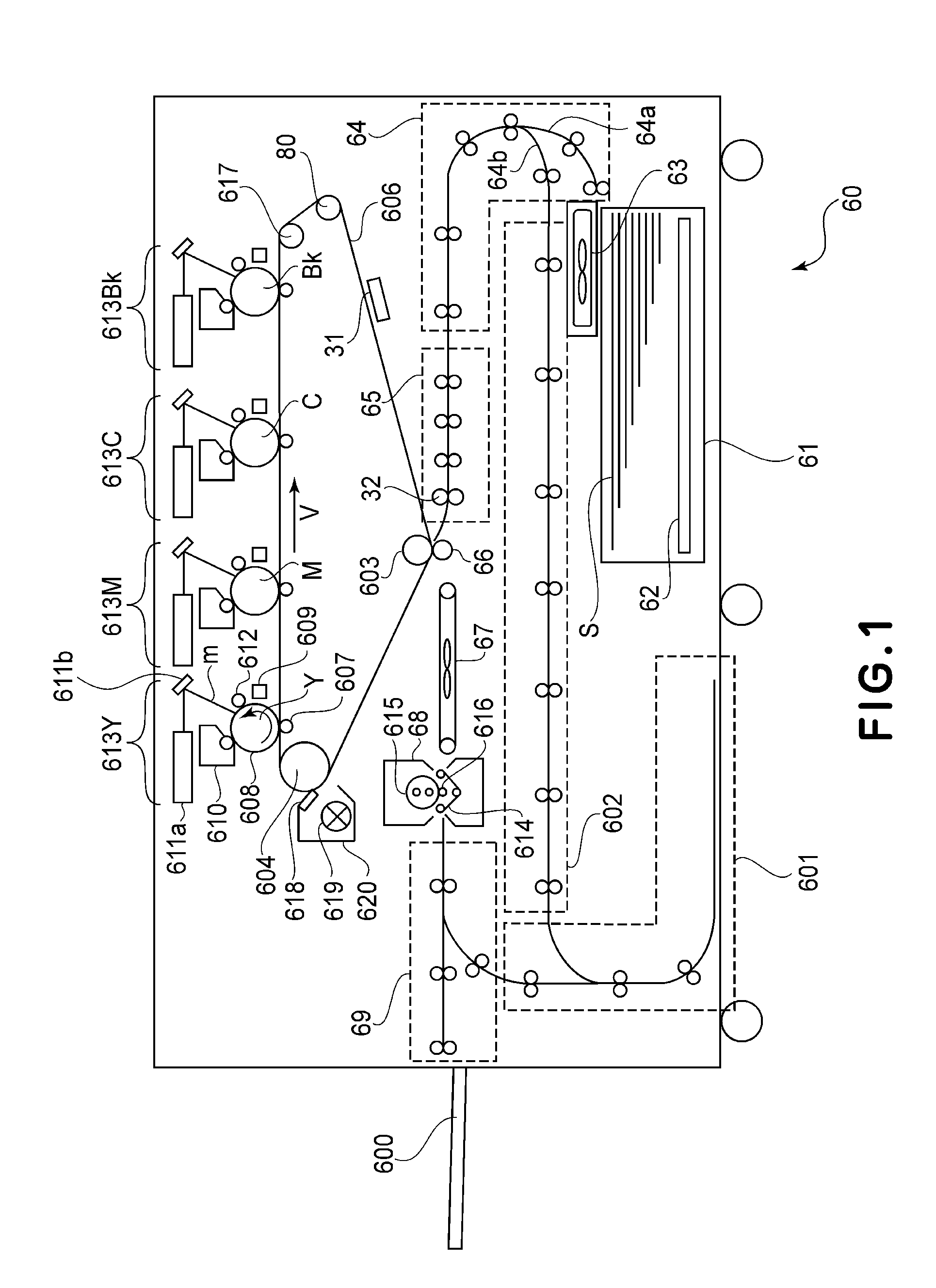
[0026]First, referring to FIG. 1, an operation of the image forming apparatus will be described. Types of the image forming apparatus may include a plurality of types such as an electrophotographic type, an offset printing type and an ink jet type. The image forming apparatus 60 shown in FIG. 1 is a color image forming apparatus of the electrophotographic type. The image forming apparatus 60 is of a so-called intermediary transfer tandem type in which four image forming portions for four colors are arranged side by side on an intermediary transfer belt. FIG. 1 is a sectional view of the image forming apparatus 60 of this type, which goes mainstream from the viewpoints of excellent compatibility with thick paper and excellent productivity.

[0027]Sheets of recording material S are stacked on a lift-up device 62 in a recording material accommodating portion 61. The recording mate...

embodiment 2

(Embodiment 2)

[0062]In this embodiment, the same constitutions as those of the intermediary transfer belt unit 700 and the image forming apparatus 60 including the intermediary transfer belt unit 700 are basically employed. Therefore, the constitution of the image forming apparatus 60 and the operation principle will be omitted from the description and a different portion will be principally explained. Further, in the following, the same portions (members) are represented by the same reference numerals or symbols and will be omitted from the description.

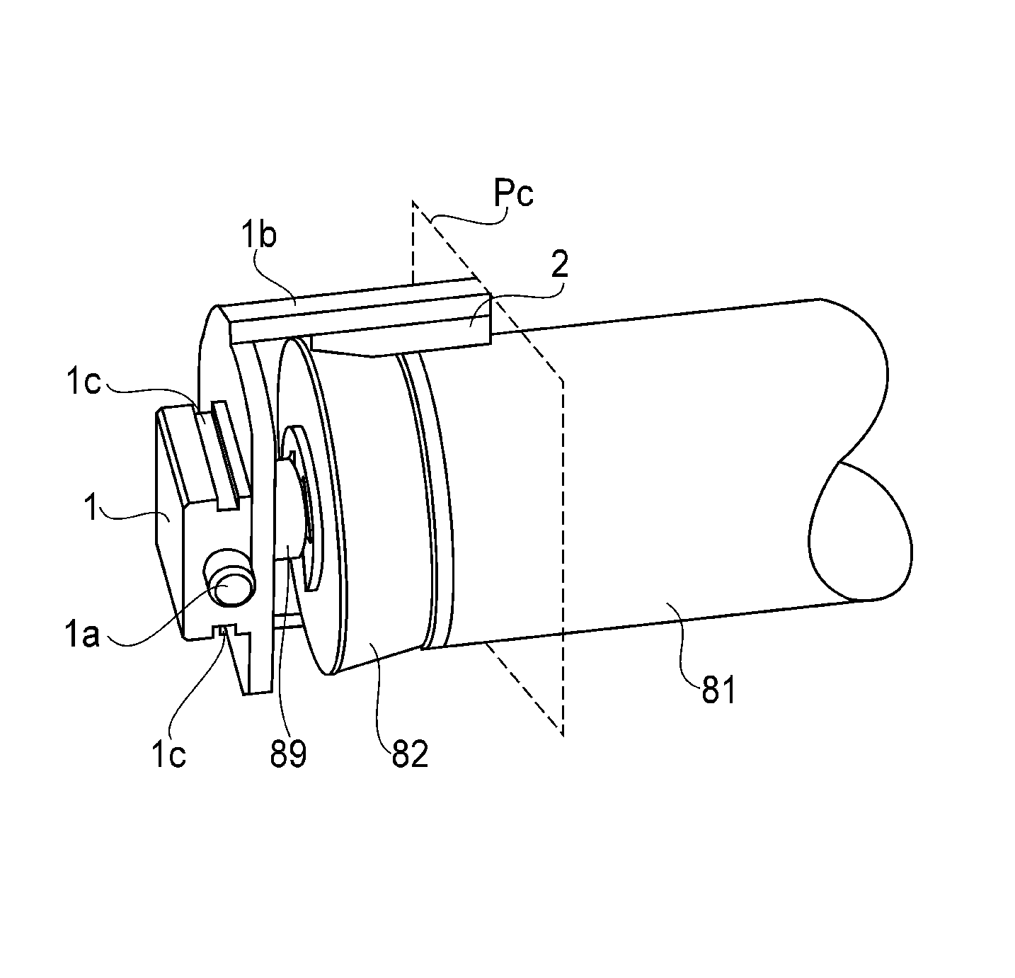
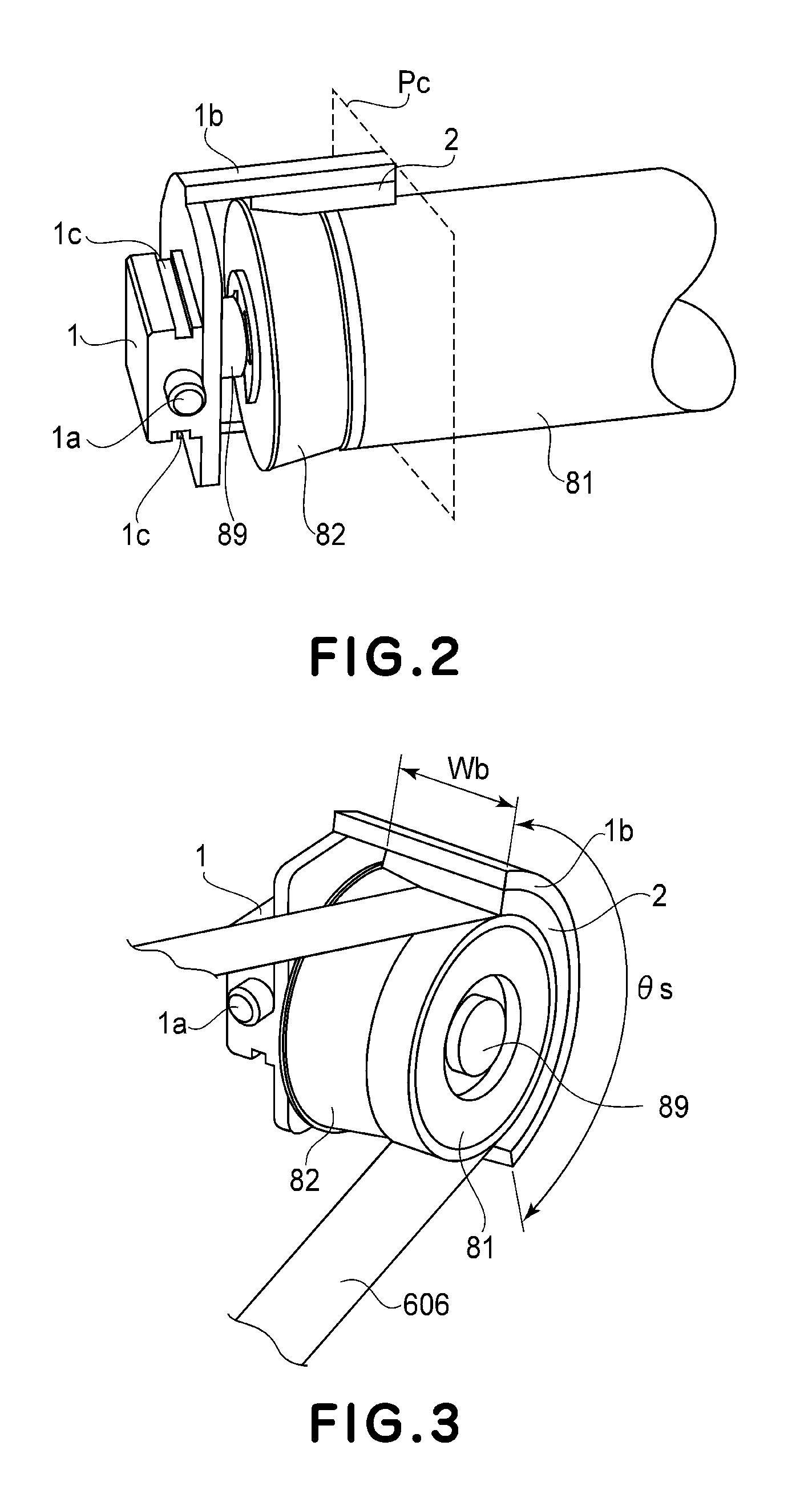
[0063]FIG. 4 is an enlarged view of the end portion of the steering roller for the intermediary transfer belt in this embodiment of the present invention. Specifically, the steering roller has the same constitution as that of the automatic center alignment mechanism described with reference to FIG. 8 and a difference portion is a supporting constitution for supporting an urging (pressing) member 2 which is a feature of the present in...

embodiment 3

(Embodiment 3)

[0070]In Embodiment 3 of the present invention, the image forming apparatus 60 including the intermediary transfer belt unit 700, the arrangement of the steering device is changed from that in Embodiment 1. The arrangement of the driving roller 604 and the steering roller 80 is interchanged. That is, the cleaning blade 618 urges the intermediary transfer belt against the steering roller 80, and the driving roller 604 is disposed between the stretching roller 617 and the inner transfer roller 603. Therefore, the constitution of the image forming apparatus 60 and the operation principle will be omitted from the description and a different portion will be principally explained. Further, in the following, the same portions (members) are represented by the same reference numerals or symbols and will be omitted from the description.

[0071]FIG. 5 is a perspective view for illustrating a relationship between a steering device 800 including the steering roller 80 and a cleaning ...


PUM


Abstract

A belt driving apparatus includes a movable belt member, a stretching member configured to stretch the belt member, and a steering unit configured to stretch the belt member and to be inclined to steer the belt member in a widthwise direction substantially perpendicular to a direction of moving of the belt member. The steering unit includes a rotatable member contacting an inner surface of the belt member and configured to be rotatable with movement of the belt member around a rotational axis of the rotatable member, with the rotational axis extending in the widthwise direction, and non-rotatable members contacting an inner surface of the belt member, provided at each opposite axial end of the rotatable member and configured not to be rotatable with movement of the belt member. In addition, a supporting member supports the rotatable member and the non-rotatable members, and is inclined by frictional force from sliding between the belt member and each of the non-rotatable members, around an axis perpendicular to the rotational axis, and urging members urge the belt member in contact with an outer surface of the non-rotatable members, with each of the urging members disposed against one of the non-rotatable members.

Description

FIELD OF THE INVENTION AND RELATED ART[0001]The present invention relates to a belt driving apparatus for driving a belt member relating to image formation. Specifically, the present invention relates to a belt unit for driving an intermediary transfer belt, a transfer belt, a photosensitive belt, etc., and also relates to an image forming apparatus such as a copying machine, a printer, a printing machine, etc., which includes the belt unit.[0002]In recent years, with speed-up of the image forming apparatus, a constitution in which a plurality of image forming portions are arranged corresponding to a belt member and image forming processes for respective colors are concurrently performed goes mainstream. For example, as a representative belt member in a full-color image forming apparatus of an electrophotographic type, the intermediary transfer belt is used. Onto a belt steering of the intermediary transfer belt, respective color toner images are successively transferred superposedl...

Claims


Application Information

Patent Timeline
Patent Type & Authority Patents(United States)
IPC IPC(8): G03G15/00G03G15/01B65G21/20
CPCG03G15/161G03G15/1615G03G15/755G03G2215/00151G03G2215/00156G03G2215/00168
Inventor YASUMOTO, TAKESHI
Owner CANON KK
Why Eureka
Try Eureka