Methods and apparatus for suspension set up

a suspension and apparatus technology, applied in the field of vehicle suspensions, can solve the problems of improper initial suspension settings, suspension to “ratchet” down into a compressed state, impact to the rider's hands, etc., and achieve the effect of enhancing the experience of the rider

Active Publication Date: 2014-09-16
FOX FACTORY
View PDF43 Cites 102 Cited by
  • Summary
  • Abstract
  • Description
  • Claims
  • Application Information

AI Technical Summary

Benefits of technology

[0014]One advantage of the disclosed technique is that the device may use the physical characteristics of the suspension component and an intended load entered by the rider to automatically calculate target values for various settings of the suspension component that should result in a properly setup vehicle suspension. The device may also receive feedback, such as using images captured by the device, to determine whether the suspension should be adjusted from the target values in order to provide the correct result. Proper setup of a vehicle suspension helps create a more enjoyable experience for the rider.

Problems solved by technology

Despite efforts to educate product managers, retailers, and end consumers on the importance of proper initial vehicle suspension set up, it is evident at event support and trail side encounters that many vehicles such as mountain bikes and motorcycles are ridden with improper initial suspension settings.
In the case of rear suspension, an improper amount of rebound damping can result in the rear of the vehicle “kicking” off the ground and pitching the rider forward after encountering a bump or sharp compression obstacle, also known as “bucking.” In the case of front suspension, an improper amount of rebound damping can cause impact to the rider's hands as the front suspension kicks back directly toward the rider.
An improper amount of rebound damping, where the amount of damping is too high, can result in the suspension not returning quickly enough to respond to the next bump in a series of bumps, ultimately causing the suspension to “ratchet” down into a compressed state.
Packing can result in the suspension being overly stiff due to retained compression through the middle to the end of a series of bumps, causing the back of the vehicle to kick off the ground and pitch the rider forward (in the case of the rear suspension) and causing the suspension to get overly stiff and steering geometry to get steep and unstable (in the case of the front suspension).

Method used


Image

  • Methods and apparatus for suspension set up
  • Methods and apparatus for suspension set up
  • Methods and apparatus for suspension set up

Examples


Embodiment Construction

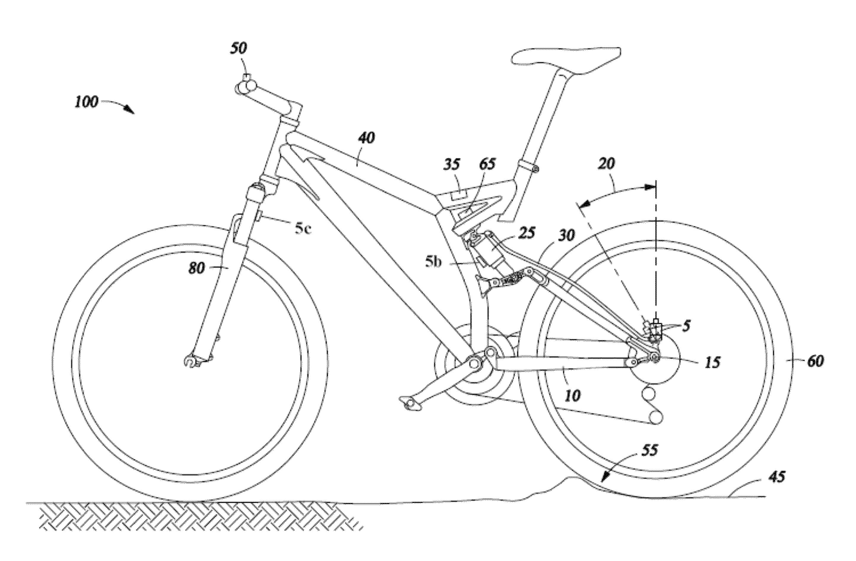
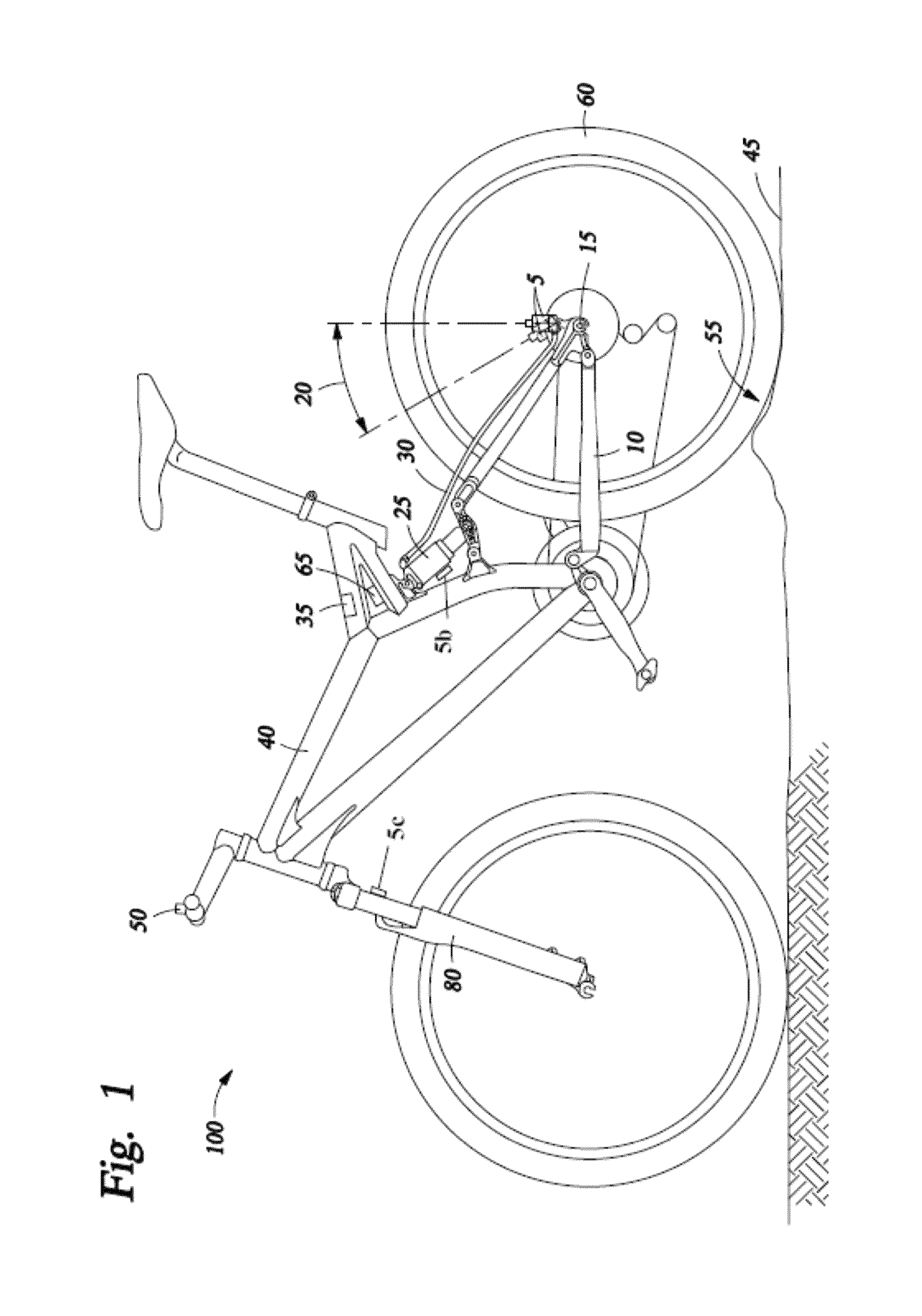
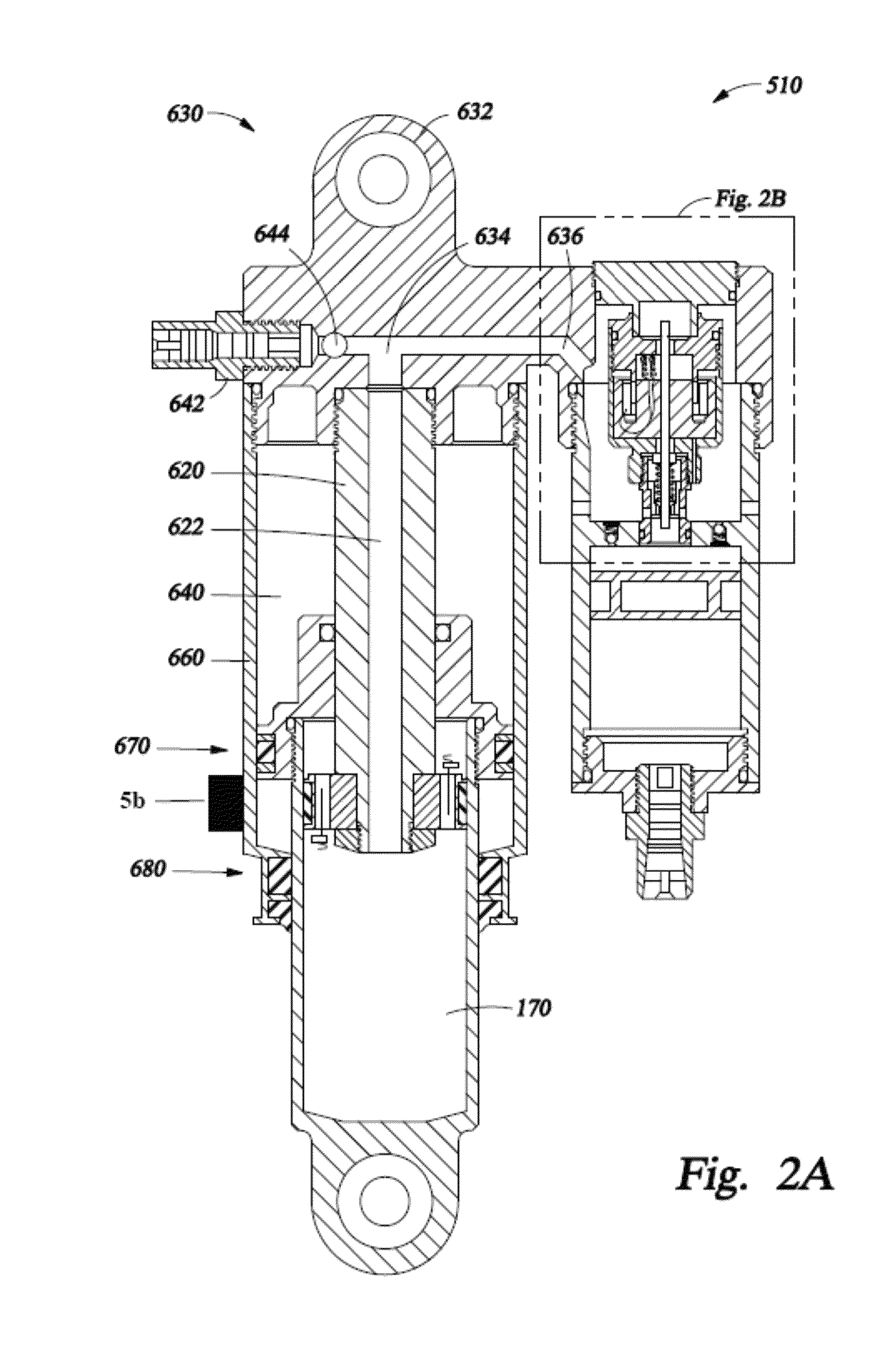
[0025]Integrated damper / spring vehicle shock absorbers often include a damper body surrounded by a mechanical spring or constructed in conjunction with an air spring. The damper often consists of a piston and shaft telescopically mounted in a fluid filled cylinder. A mechanical spring may be a helically wound spring that surrounds the damper body. Various integrated shock absorber configurations are described in U.S. Pat. Nos. 6,311,962; 6,135,434; 5,044,614; 5,803,443; 5,553,836; and 7,293,764; each of which is herein incorporated by reference in its entirety.

[0026]Some shock absorbers utilize gas as a spring medium in place of, or in addition to, mechanical springs. Gas spring type shock absorbers, such as gas spring shock absorbers having integral dampers, are described in U.S. Pat. Nos. 6,135,434; 6,360,857; and 6,311,962, each of which is herein incorporated by reference in its entirety. U.S. Pat. No. 6,360,857, which is incorporated herein by reference in its entirety, shows a...


PUM


Abstract

A method and apparatus are disclosed that assist a user in performing proper setup of a vehicle suspension. A user may utilize a device equipped with an image sensor to assist the user in proper setup of a vehicle suspension. The device executes an application that prompts the user for input and instructs the user to perform a number of steps for adjusting the suspension components. In one embodiment, the application does not communicate with sensors on the vehicle. In another embodiment, the application may communicate with various sensors located on the vehicle to provide feedback to the device during the setup routine. In one embodiment, the device may analyze a digital image of a suspension component to provide feedback about a physical characteristic of the component.

Description

CROSS-REFERENCE TO RELATED APPLICATIONS[0001]This application claims benefit of U.S. Provisional Patent Application Ser. No. 61 / 533,712, filed Sep. 12, 2011, and U.S. Provisional Patent Application Ser. No. 61 / 624,895, filed Apr. 16, 2012. This application is related to U.S. patent application Ser. No. 13 / 022,346, which claims benefit of U.S. Provisional Patent Application Ser. No. 61 / 302,070, filed Feb. 5, 2010, and U.S. Provisional Patent Application 61 / 411,901, filed Nov. 9, 2010, and U.S. patent application Ser. No. 12 / 727,915, filed Mar. 19, 2010, which claims benefit of U.S. Provisional Patent Application Ser. No. 61 / 161,552, filed Mar. 19, 2009, and U.S. Provisional Patent Application Ser. No. 61 / 161,620, filed Mar. 19, 2009, and U.S. patent application Ser. No. 12 / 773,671, filed May 4, 2010, which claims benefit of U.S. Provisional Patent Application Ser. No. 61 / 175,422, filed May 4, 2009. Each of the aforementioned patent applications is herein incorporated by reference in ...

Claims


Application Information

Patent Timeline
Patent Type & Authority Patents(United States)
IPC IPC(8): G06K9/00B60R21/00B60G17/018
CPCG06T7/004G06T7/0081B60G2600/182B60G17/018B62K2025/044B60G17/04B60G17/015G06T2210/22G06T2207/20021B60G2401/142B62K2025/047G06T2207/30248B60G17/06B62K25/04B60G2600/04B60G17/019B62K25/286B60G17/017B60G17/0424B60G2204/61B60G2206/99B60G2300/12B60G2401/14B60G2500/102B60G2500/30B60G2600/20B60G2600/704B62K2025/048B62J45/42B62J45/41G06T2207/30252
Inventor GALASSO, MARIOFRANKLIN, JOSEPHLAIRD, ANDREWBASS, CHARLESBAVETTA, RYAN
Owner FOX FACTORY
Why Eureka
Try Eureka