Mechanical joint for CuZnFe alloy heat exchanger and method

a technology of mechanical joints and cuznfe alloys, applied in heat exchange apparatus, metal-working apparatus, lighting and heating apparatus, etc., can solve the problems of poor tolerances in the geometry of header holes or tubes, prone to leakage, and weak joint strength

Active Publication Date: 2014-09-23
WESTINGHOUSE AIR BRAKE TECH CORP
View PDF17 Cites 2 Cited by
  • Summary
  • Abstract
  • Description
  • Claims
  • Application Information

AI Technical Summary

Benefits of technology

[0009]In a first aspect, the present invention generally provides a process for the creation of a flat-round tube-to-header joint in a CuproBraze™ heat exchanger wherein the flat-round tube-to-header joint is disposed between a tube and a header having a generally circular opening, having a first predetermined diameter, formed on a first side thereof for receiving one end of a tube, and provides at least one generally circular end having a second predetermined diameter on the tube to fit into the generally circular opening formed in the header. The method further provides a predetermined temper on at least one generally circular end which is at least sufficient to enable cold working of the at least one generally circular end to prevent premature failures of the flat-round tube-to-header joint. The flat-round tube-to-header joint is formed by inserting one end of the tube into the first side of the header and forming the flat-round tube-to-header joint between one end of the tube and the header.
[0013]Another object, of the present invention, is to provide a flat-round tube-to-header joint in a CuproBraze™ heat exchanger which eliminates the brazed tube-to-header joint in a CuproBraze™ heat exchanger.
[0014]Still another object, of the present invention, is to provide a flat-round tube-to-header joint in a CuproBraze™ heat exchanger which significantly reduces premature failures of such flat-round tube-to-header joints.
[0015]Yet another object, of the present invention, is to provide a flat-round tube-to-header joint in a CuproBraze™ heat exchanger that reduces the row pitch in both the staggered and parallel style arrays.
[0017]A still further object, of the present invention, is to provide a flat-round tube-to-header joint in a CuproBraze™ heat exchanger that allows for easier repair of a leaking tube-to-header joint.

Problems solved by technology
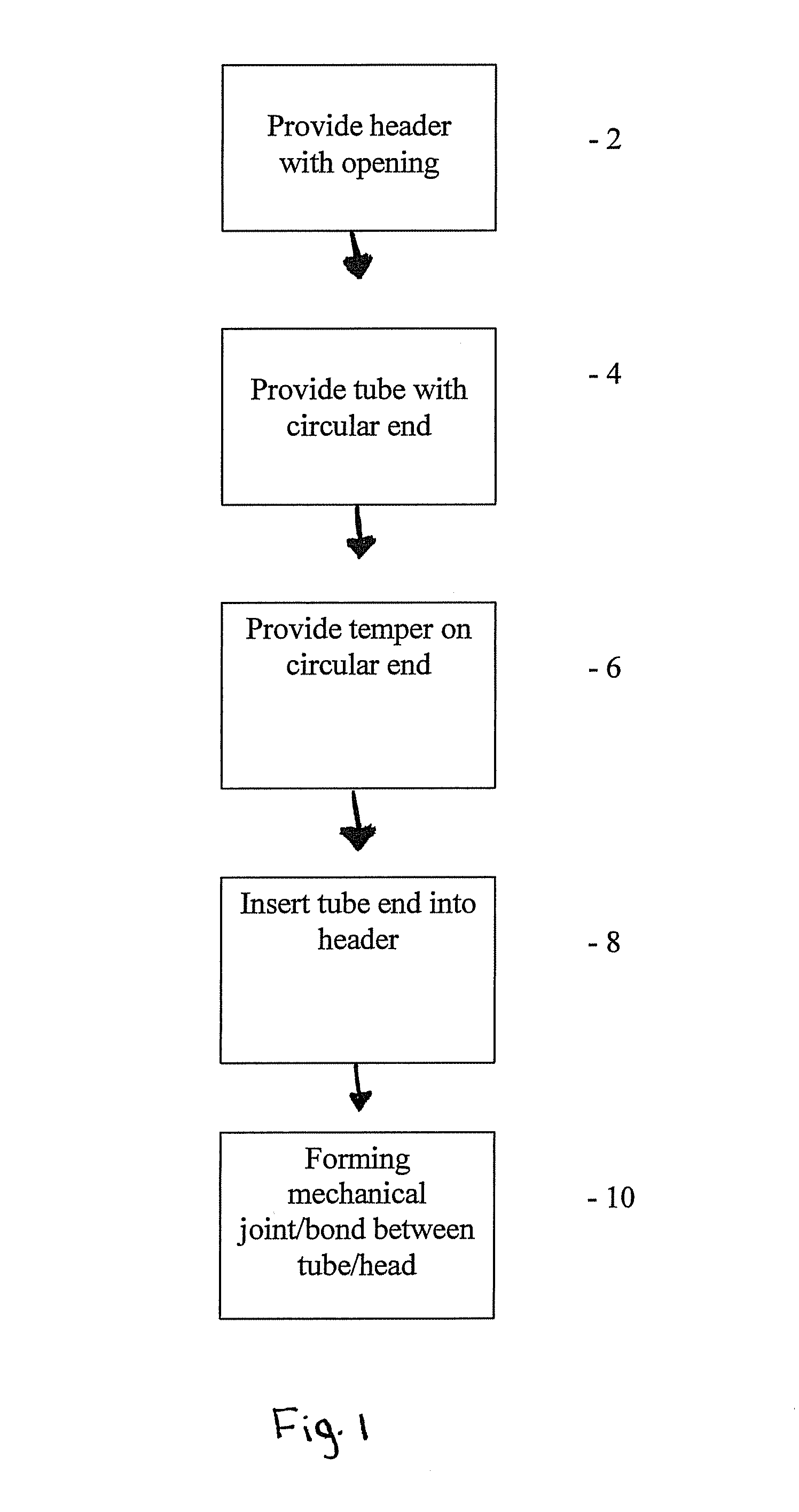
This joint, while being relatively strong, is prone to leaks after the initial brazing of the core if the process is not under precise control.
Many variables can lead to leaks developing at the joint.
These variables include poor tolerances in the header hole or tube geometry, poor paste application on the tube-to-header joint, poor heat profiles during brazing, as well as other factors.
The brazed tube-to-header joint is also prone to premature failure.
Unfortunately, these prior art bonding processes add thermal stress to the tubes at their respective bonding locations, thereby increasing the grain size of the tube and reducing the tensile strength of the material at this point.
A reduction in such tensile strength can and often times does result in pressure cycle fatigue and failure.
This fatigue is also a result of the stresses applied during thermal cycling.
During the thermal cycle, deformation of the header may occur as a result of the weight of the heat exchanger and the coolants therein, thereby weakening the core-to-header assembly, which leads to failure of the bond.

Method used


Image

  • Mechanical joint for CuZnFe alloy heat exchanger and method
  • Mechanical joint for CuZnFe alloy heat exchanger and method
  • Mechanical joint for CuZnFe alloy heat exchanger and method

Examples


Embodiment Construction

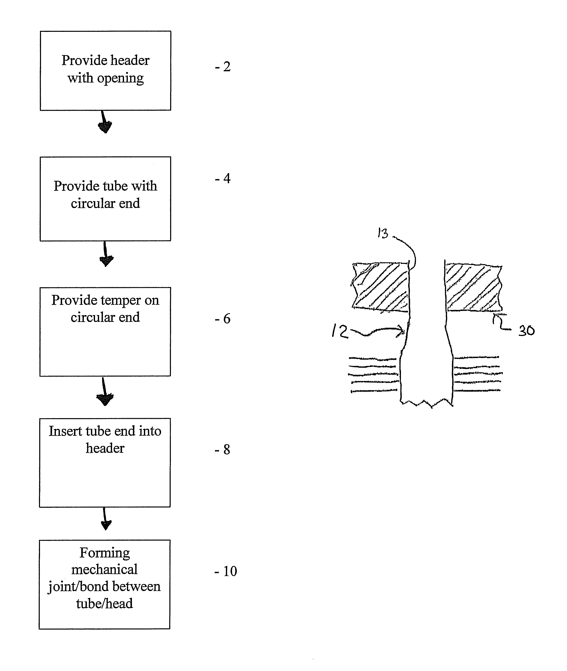
[0024]The present invention provides a method of creating a flat-round tube-to-header joint in a CuproBraze™ heat exchanger. Although the flat-round process is not currently being used in the CuproBraze™ process today, it is being used in the manufacturing process of traditional soldered plate-fin type radiators. For example, U.S. Pat. No. 3,857,151 describes the original process of making the flat-round joint and this process has been refined and copied by multiple manufacturers since its initial inception.

[0025]The applicants of the present invention have developed the means to modify and use this process on CuproBraze™ heat exchangers successfully. The modified process is slightly different when compared to soldered radiators because of a different brass material that is used for the tubes. The CuproBraze™ tube brass is a special anneal resistant alloy that does not anneal as much as traditional brass during the brazing process.

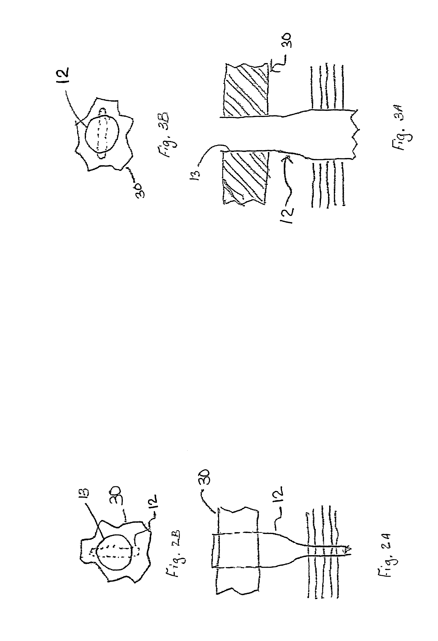
[0026]The ends 13 of the tubes 12, as shown in FIGS....


PUM


Abstract

A method of creating a flat-round tube-to-header joint in a CuproBraze™ heat exchanger wherein the flat-round tube-to-header joint is disposed between a tube and a header having a generally circular opening having a first predetermined diameter formed on a first side thereof for receiving one end of a tube, and provides at least one generally circular end having a second predetermined diameter on the tube to fit into the generally circular opening of in the header. The method further provides a predetermined temper on at least one generally circular end which is at least sufficient to enable cold working of at least one generally circular end to prevent premature failures of the flat-round tube-to-header joint. The flat-round tube-to-header joint is formed by inserting one end of the tube into the first side of the header and forming the flat-round tube-to-header joint between one end of the tube and the header.

Description

CROSS REFERENCE TO RELATED APPLICATION[0001]This patent application is related to and claims benefit from provisional patent application Ser. No. 60 / 527,432 filed Dec. 5, 2003.FIELD OF THE INVENTION[0002]The present invention relates, in general, to heat transfer products using a CT or Serpentine fin style core, which include but are not limited to, radiators, shell and tube type heat exchangers, charge air coolers, oil coolers, and fuel coolers and, more particularly, the instant invention relates to a flat-round tube-to-header type joint used in a CuproBraze™ or CuZnFe alloy, heat exchanger.BACKGROUND OF THE INVENTION[0003]Currently CuproBraze™, or CuZnFe alloy heat exchangers use a brazed tube-to-header type joint. This joint, while being relatively strong, is prone to leaks after the initial brazing of the core if the process is not under precise control. Many variables can lead to leaks developing at the joint. These variables include poor tolerances in the header hole or tube ...

Claims


Application Information

Patent Timeline
Patent Type & Authority Patents(United States)
IPC IPC(8): F28F9/02B21D53/02F28F9/16
CPCF28F9/16Y10T29/4935
Inventor SMITH, GEOFFKORTH, JAY
Owner WESTINGHOUSE AIR BRAKE TECH CORP
Why Eureka
Try Eureka