Spark plug

a technology of spark plugs and plugs, applied in spark plugs, machines/engines, mechanical equipment, etc., can solve problems such as durability degradation, and achieve the effects of preventing breakage at the shoulder portion, reducing vibration, and improving durability and ignition performan

Active Publication Date: 2014-09-23
NGK SPARK PLUG CO LTD
View PDF26 Cites 2 Cited by
  • Summary
  • Abstract
  • Description
  • Claims
  • Application Information

AI Technical Summary

Benefits of technology

[0024]According to the spark plug of configuration 1, the noble metal tip is relatively elongated such that the shortest distance between the fusion zone and the distal end surface of the noble metal tip is 0.8 mm or greater as measured on the outer side surface of the noble metal tip. Therefore, durability and ignition performance can be improved.
[0025]Meanwhile, when the noble metal tip is relatively elongated, as mentioned above, breakage at the center electrode, etc., is a concern. However, according to the above configuration 1, the acute angle θ1 formed by the straight lines L1 and L2 assumes a relatively small value of 72° or less. That is, in view that stress concentrates where cross-sectional area changes to a relatively great extent, configuration is determined such that the rate of change in cross-sectional area along the axis is relatively low at the shoulder portion of the center electrode, breakage at the shoulder portion being a particular concern. Therefore, the concentration of stress associated with vibration on the shoulder portion can be effectively restrained, whereby breakage at the shoulder portion can be reliably prevented.
[0026]Also, the fusion zone formed at a distal end subportion of the shoulder portion is configured such that the outside diameter of the fusion zone as measured at the distal end of the fusion zone is smaller than that as measured at the proximal end of the fusion zone (that is, the contour of the fusion zone is tapered). Therefore, a boundary region between the shoulder portion and the fusion zone can be prevented from having a steeply bent shape (a shape involving a sharp change in cross-sectional area), whereby stress associated with vibration can be more reliably prevented from concentrating on the boundary region or its vicinity. As a result, breakage at the boundary region and its vicinity can be more reliably restrained.
[0027]Thus, according to the spark plug of configuration 1, breakage resistance of the shoulder portion, the boundary region, etc., can be improved; eventually, the effect of improving durability and ignition performance associated with provision of the noble metal tip can be exhibited over a long period of time.
[0028]According to the spark plug of configuration 2, the angle θ2 formed by the straight line L3 and the straight line L4 is determined so as to satisfy the relational expression θ1−θ2≦50°. Therefore, in a region ranging from the shoulder portion to the fusion zone, the rate of change in cross-sectional area along the direction of the axis can be further reduced; eventually, stress concentration on the shoulder portion and the fusion zone can be further reliably prevented. As a result, breakage resistance can be further improved.
[0029]According to the spark plug of configuration 3, the outlines of the shoulder portion are rectilinear; thus, stress concentration on the shoulder portion can be further reliably prevented. As a result, breakage resistance can be further improved.

Problems solved by technology

In a spark plug of such a type that the forward (or distal) end surface of a ground electrode faces the side surface of a distal end portion of a noble metal tip to thereby generate spark discharges across a spark discharge gap between the two members substantially along a direction orthogonal to the axis (a so-called lateral discharge type), if the ground electrode and a fusion zone of joining a center electrode and the noble metal tip are close to each other, an abnormal spark discharge may be generated between the fusion zone and the ground electrode, potentially resulting in a deterioration in durability.

Method used


Image

  • Spark plug
  • Spark plug
  • Spark plug

Examples


Embodiment Construction

Modes for Carrying Out the Invention

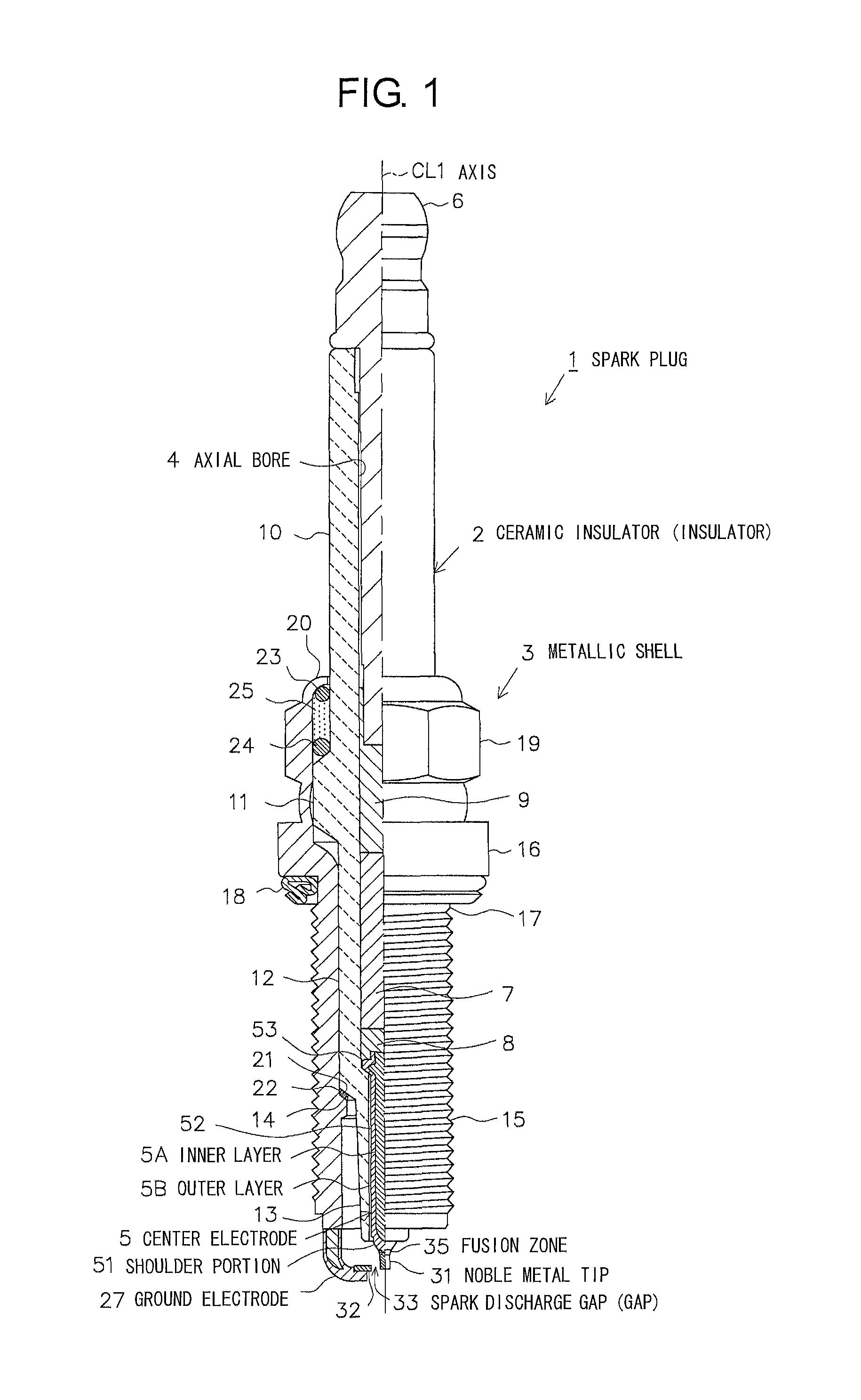
[0051]An embodiment of the present invention will next be described with reference to the drawings. FIG. 1 is a partially cutaway front view showing a spark plug 1. In FIG. 1, the direction of an axis CL1 of the spark plug 1 is referred to as the vertical direction. In the following description, the lower side of the spark plug 1 in FIG. 1 is referred to as the forward side of the spark plug 1, and the upper side as the rear side.

[0052]The spark plug 1 includes a ceramic insulator 2, which is the insulator in the present invention, and a tubular metallic shell 3 which holds the ceramic insulator 2 therein.

[0053]The ceramic insulator 2 is formed from alumina or the like by firing, as well known in the art. The ceramic insulator 2, as viewed externally, includes a rear trunk portion 10 formed on the rear side; a large-diameter portion 11, which is located forward of the rear trunk portion 10 and projects radially outward; an intermediate trunk porti...


PUM


Abstract

A spark plug includes a ceramic insulator, a center electrode, a metallic shell, and a ground electrode. The center electrode has a shoulder portion at a forward end portion, which tapers forward with respect to the axial direction. A noble metal tip is joined to the forward end portion of the center electrode through a fusion zone. A spark discharge gap is formed between the noble metal tip and the ground electrode. The shortest distance between the fusion zone and a forward end surface of the noble metal tip is 0.8-1.2 mm. The outside diameter of the fusion zone as measured at a forward end of the fusion zone is smaller than that as measured at a rear end of the fusion zone. An acute angle θ1 formed by a straight line L1 and a straight line L2 satisfies the relational expression θ1≦72°.

Description

CROSS-REFERENCE TO RELATED PATENT APPLICATIONS[0001]This application is a U.S. National Phase Application under 35 U.S.C. §371 of International Patent Application No. PCT / JP2010 / 006898, filed Nov. 26, 2010, and claims the benefit of Japanese Patent Application No. 2010-033548, filed Feb. 18, 2010, all of which are incorporated by reference herein. The International Application was published in Japanese on Aug. 25, 2011 as International Publication No. WO / 2011 / 101939 under PCT Article 21(2).FIELD OF THE INVENTION[0002]The present invention relates to a spark plug for use in an internal combustion engine or the like.BACKGROUND OF THE INVENTION[0003]A spark plug for use in a combustion apparatus, such as an internal combustion engine, includes, for example, a center electrode extending in the axial direction, an insulator provided externally of the outer circumference of the center electrode, a cylindrical metallic shell mounted to the outside of the insulator, and a ground electrode e...

Claims


Application Information

Patent Timeline
Patent Type & Authority Patents(United States)
IPC IPC(8): H01T13/20F02P13/00H01T13/39
CPCH01T13/39F02P13/00
Inventor KASUYA, YUJIBAN, KENJI
Owner NGK SPARK PLUG CO LTD
Why Eureka
Try Eureka