
Electric three-way valve

a three-way valve, electric technology, applied in the direction of valve operating means/release devices, transportation and packaging, light and heating apparatus, etc., can solve the problem of not taking into account the shape of the valve core, which may easily and smoothly slide on the valve seat, etc., to increase the size of the coil, and reduce the volume of the occupied space

Active Publication Date: 2014-09-30
ZHEJIANG SANHUA INTELLIGENT CONTROLS CO LTD
View PDF15 Cites 6 Cited by
  • Summary
  • Abstract
  • Description
  • Claims
  • Application Information

AI Technical Summary

Benefits of technology

[0007]The invention is made in view of the above-described problems, and it is an object of the invention to provide an electric three-way valve capable of realizing a decrease in the volume of an occupied space by preventing an increase in the size of a coil, maintaining a valve core in a satisfactory parallel state, and ensuring the sliding of the valve core in the rotation direction in a valve seat.
[0008]Further, it is another object of the invention to provide an electric switching valve capable of realizing a decrease in the volume of an occupied space by preventing an increase in the size of a coil, maintaining a valve core in a satisfactory parallel state, and ensuring the sliding of the valve core in the rotation direction in a valve seat.

Problems solved by technology

Furthermore, in the typical valve core which rotates in a sliding manner, the shape of the valve core which may easily and smoothly slide on the valve seat is not taken into consideration.

Method used


Image

  • Electric three-way valve
  • Electric three-way valve
  • Electric three-way valve

Examples


Embodiment Construction

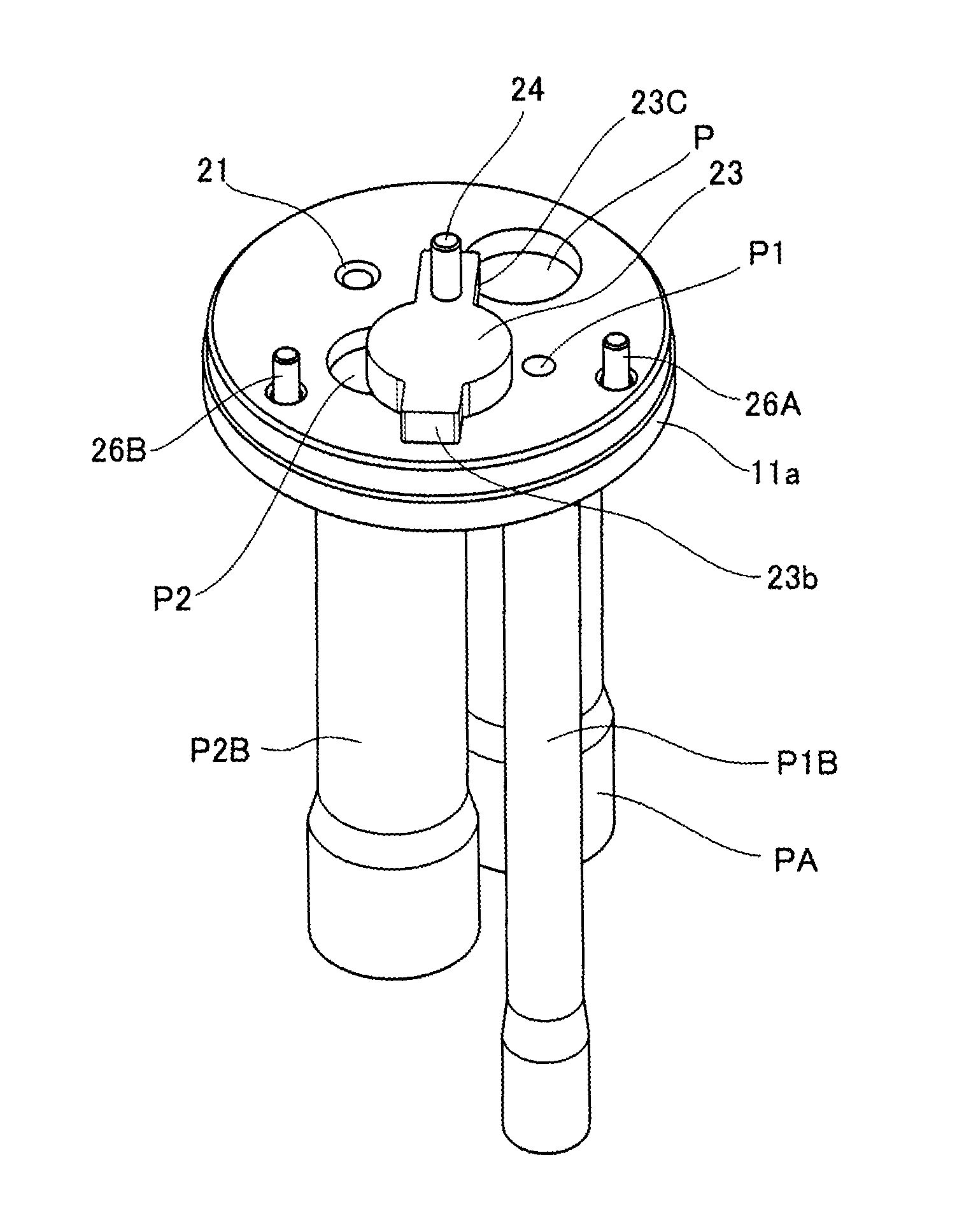
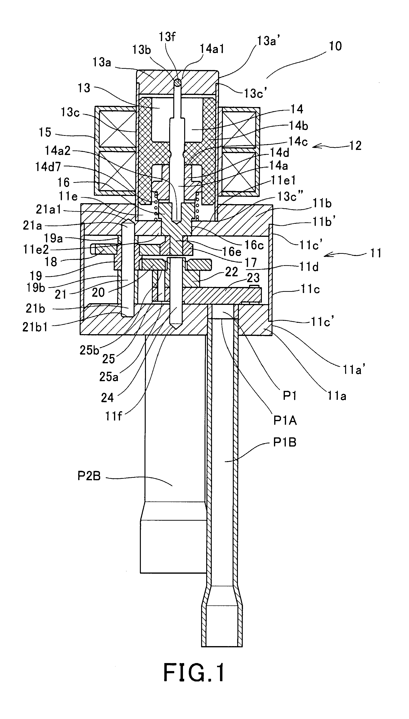
[0037]An electric three-way valve 10 as an electric switching valve illustrated in FIG. 1 includes a cylindrical casing 11 which is formed of a metal material, for example, stainless steel and a motor unit 12. The motor unit 12 includes a cylindrical housing 13 which is formed of a non-magnetic metal material, for example, stainless steel, a rotor 14 and a rotor shaft 14a which are disposed inside the housing, and a fixed coil 15 which is laid on the outside of the housing 13 and serves as a stator to drive the rotor 14, where the motor unit 12 is separated from the casing 11 and is disposed at the upper outer side of the casing 11 in the drawings.

[0038]The cylindrical casing 11 includes a disk-like valve seat (which is also called a valve seat surface) 11a which is formed of a metal material, for example, stainless steel, a disk-like plane plate 11b which is disposed so as to face the valve seat 11a, serves as an upper end surface, and is formed of a metal material, for example, st...


PUM


Abstract

An electric three-way valve comprises: an input port, a plurality of output ports and a valve core which rotates in a sliding manner in the valve seat by a driving force of a motor unit, wherein the valve core selectively opens or closes the plurality of output ports, the motor unit is attached as a separated constituent to an outside of an upper end surface of a cylindrical casing introducing refrigerant, the valve core is driven by a gear unit which transmits the driving force of the motor unit and is disposed inside the cylindrical casing, the cylindrical casing includes one opening portion and a side wall with an apex portion, a housing which is fixed to a cylindrical wall portion of the apex portion and is equipped with the motor unit is uprightly formed in the other opening portion, and the housing is attached to the cylindrical casing.

Description

BACKGROUND OF THE INVENTION[0001]1. Field of the Invention[0002]The present invention relates to an electric three-way valve which circulates refrigerant of an air-conditioner and a refrigerator and switches a passageway.[0003]2. Description of the Related Art[0004]In general, there is known a valve which uses a motor, for example, a step motor, installs a gear in a shaft end portion of a rotor of the motor, and blocks one passageway opened to a valve seat by rotating a valve core in the valve seat in a sliding manner using a driving force generated by the meshing between the gear and a gear driving the valve core (see Japanese Patent Literature 1, that is, JP 03-28583 A). Furthermore, there is known a valve which controls an opening degree of an opening by a valve core driven so as to slide on a valve seat by a driving force generated by a gear as described above (see Japanese Patent Literature 2, that is, JP 2000-346227 A).[0005]In the typical valve which uses the valve core rotat...

Claims


Application Information

Patent Timeline
Patent Type & Authority Patents(United States)
IPC IPC(8): F16K11/06F16K11/14F16K31/04F25B5/02F16K11/085
CPCF16K31/041F16K31/04F16K11/0743Y10T137/8782F16K11/06Y10T137/87732Y10T137/86855F25B41/04F25B41/20F16K11/072
Inventor LIN, YANWEIHUI, XUMINGFENG, DINGSHUAICHEN, BIN
Owner ZHEJIANG SANHUA INTELLIGENT CONTROLS CO LTD
Learn More