
Aircraft structural assembly and associated assembling method

a technology for aircraft and structural parts, applied in the direction of structural elements, aircraft floors, sheet joining, etc., can solve the problems of increasing assembly costs, reducing the service life of aircraft, so as to achieve the effect of few or no transverse stresses

Inactive Publication Date: 2014-09-30
DASSAULT AVIATION
View PDF9 Cites 10 Cited by
  • Summary
  • Abstract
  • Description
  • Claims
  • Application Information

AI Technical Summary

Benefits of technology

The invention relates to an aircraft structure that connects a structural wall to a composite wall in a way that can withstand high stress. This structure is designed to be cost-effective and minimize any side loads that may occur.

Problems solved by technology

Such an assembly however does not give entire satisfaction.
Indeed, the presence of intermediate metal fittings significantly increases the weight of the aircraft, taking into account the individual weight of the fitting, as well as composite wall overthicknesses required for attaching the fitting.
Further, the presence of the fittings increases the cost of the assembly and makes its assembling more complex, while reducing robustness with regard to resistance to corrosion.
Further, in the particular case of a wing, these connections are located at the tanks of fuel contained in the wing and therefore are sources of potential fuel leaks.

Method used


Image

  • Aircraft structural assembly and associated assembling method
  • Aircraft structural assembly and associated assembling method
  • Aircraft structural assembly and associated assembling method

Examples


Embodiment Construction

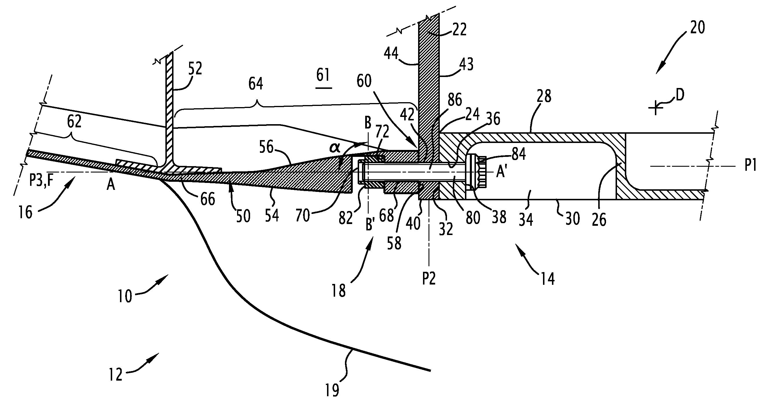
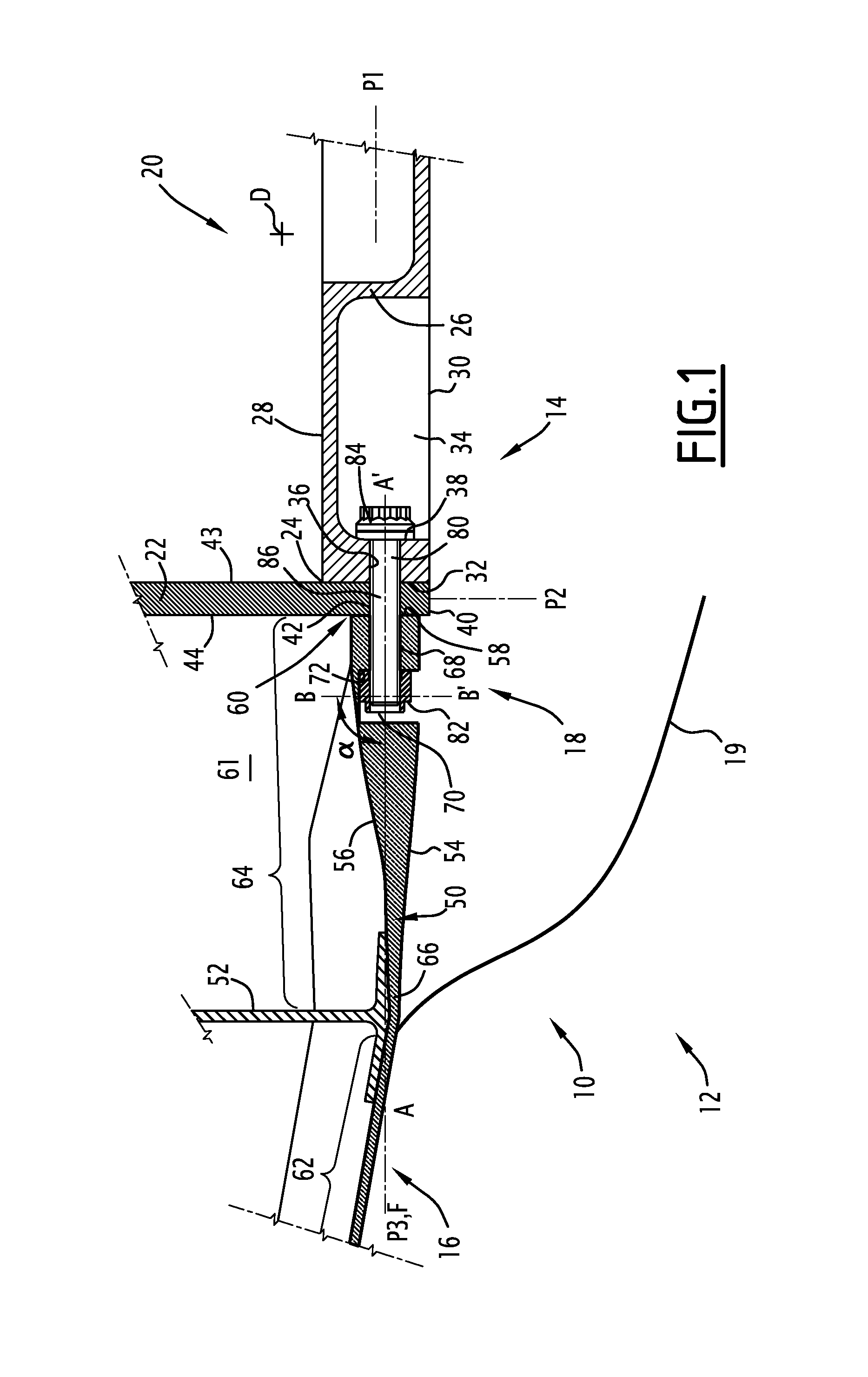
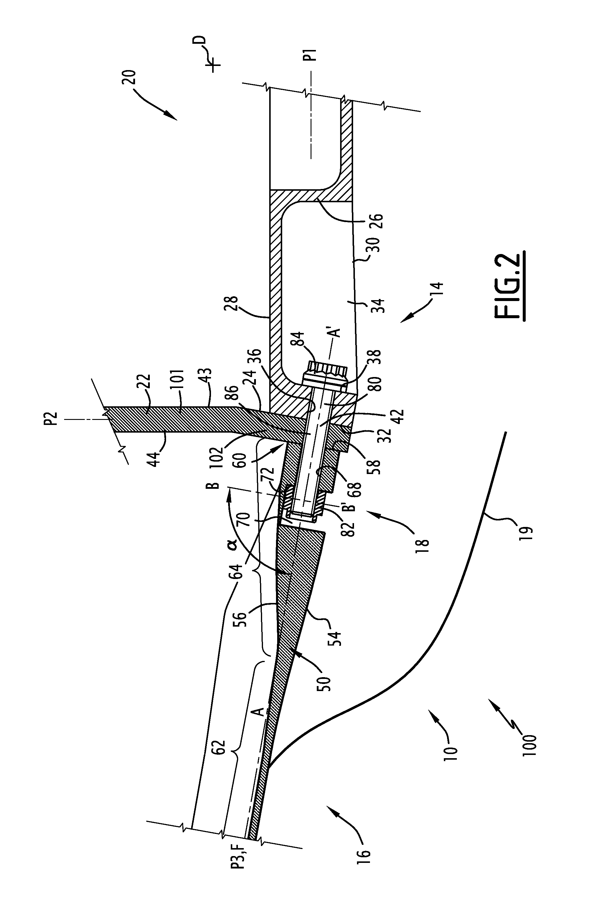
[0051]FIG. 1 illustrates a structural assembly 10 according to the invention of a first aircraft 12. This structural assembly 10 includes a first structure element 14 and a second structural element 16 at least partly made in a composite material, the second structure element 16 being assembled on the first structure element 14 via attachment means 18.

[0052]The first structure element 14 is for example a central fuselage box, in metal material. The second structure element 16 is for example a wing or a tail comprising skin panels intended to be attached onto the first structure element 14 while being stressed by a normal force when the aircraft moves in a mass of air, in particular during a flight.

[0053]In the particular example illustrated in FIG. 1, the first structure element 14 is a central fuselage box and the second structure element 16 is a wing. It further comprises a so-called “Karman” lower wall 19 positioned underneath the first element 14 and the second element 16.

[0054]...


PUM


Abstract

An assembly includes a structural wall and a composite wall extending in the extension of the structural wall and defining a second section positioned facing a first section of the wall. The assembly includes an elongated traction element received in a first passage made in the structural wall, the first passage opening out into the first section and into a cell made in the structural wall. The composite wall defines a second passage opening out into the second section and receiving the elongated element. The assembly includes a locking member added onto the elongated element. The composite wall delimits an access cavity connecting an outer surface of the composite wall to the second passage. The locking member is received into the access cavity.

Description

CROSS REFERENCE TO RELATED APPLICATIONS[0001]The present application claims priority under 35 U.S.C. §119 to French Patent Application No. 10 02378, filed Jun. 4, 2010, which is incorporated herein by reference.FIELD OF THE INVENTION[0002]The present invention relates to an aircraft structural assembly for a composite wall.BACKGROUND OF THE INVENTION[0003]Prior art aircraft structural assemblies can include[0004]a structural supporting wall, the structural wall having a first section along a first edge;[0005]a composite wall assembled on the structural wall, the composite wall extending in the extension of the structural wall beyond the first edge and defining a second section positioned facing the first section;[0006]means for attaching the structural wall with the composite wall including at least one elongated traction element received in a first passage made in the structural wall, the first passage opening out into the first section and into a cell made in the structural wall.[...

Claims


Application Information

Patent Timeline
Patent Type & Authority Patents(United States)
IPC IPC(8): B64C1/26B64C1/00F16B5/02F16B37/04
CPCB64C1/26F16B37/047F16B5/0291
Inventor ANDRE, STEPHANE
Owner DASSAULT AVIATION
Learn More