Check patentability & draft patents in minutes with Patsnap Eureka AI!

Wheelchair with lever drivetrain

a technology of lever drivetrain and wheel chair, which is applied in the field of wheel chair, can solve the problems of double bus fares, limited ability of disabled individuals in the developing world to travel to work and even be a functional member of their society, and profoundly affect people with disabilities. achieve the effect of increasing torque and speed

Active Publication Date: 2014-09-30
GLOBAL RES INNOVATION & TECH
View PDF12 Cites 5 Cited by
  • Summary
  • Abstract
  • Description
  • Claims
  • Application Information

AI Technical Summary

Benefits of technology

The patent describes a manually powered wheelchair with levers that control the movement of the wheelchair. The wheelchair has two rear wheels and a front wheel. The levers can be adjusted to change the mechanical advantage of the wheelchair, which affects its speed and torque. The wheelchair also has a freewheel that can be activated by the levers. The wheelchair is powered by a chain and a chainring, with gear ratios between 4:1 and 3:1. The levers can be adjusted to control the wheelchair's movement, and the wheelchair can be moved by differentially powering or applying the brakes. The patent's technical effects include improved control and efficiency of the wheelchair's movement.

Problems solved by technology

People with disabilities are profoundly affected by the lack of access to mobility aids.
Moreover, discrimination in the developing world has even resulted in double-charging for bus fares, simply due to an alleged added transportation cost for a wheelchair (Amos G. Winter, V., Assessment of Wheelchair Technology in Tanzania.
In short, the ability of disabled individuals in the developing world to travel to a job and even to be a functional member of their society is limited by the lack of readily available mobility aids.
Conventional, western-style wheelchairs have limited usefulness to the disabled in developing countries.
These wheelchairs are inefficient to propel and can be exhausting to use over long distances and on the rough terrain typical in such countries.
Furthermore, these wheelchairs are most often manufactured abroad with components that are not locally-available, and thus once a part on the wheelchair breaks or exhausts its expected service life, the original part cannot be readily replaced (if at all) with a spare or replacement part.
It has even been found that locally-manufactured wheelchairs still employ custom and relatively expensive components that prevent would-be purchasers from owning them.

Method used


Image

  • Wheelchair with lever drivetrain
  • Wheelchair with lever drivetrain
  • Wheelchair with lever drivetrain

Examples


Embodiment Construction

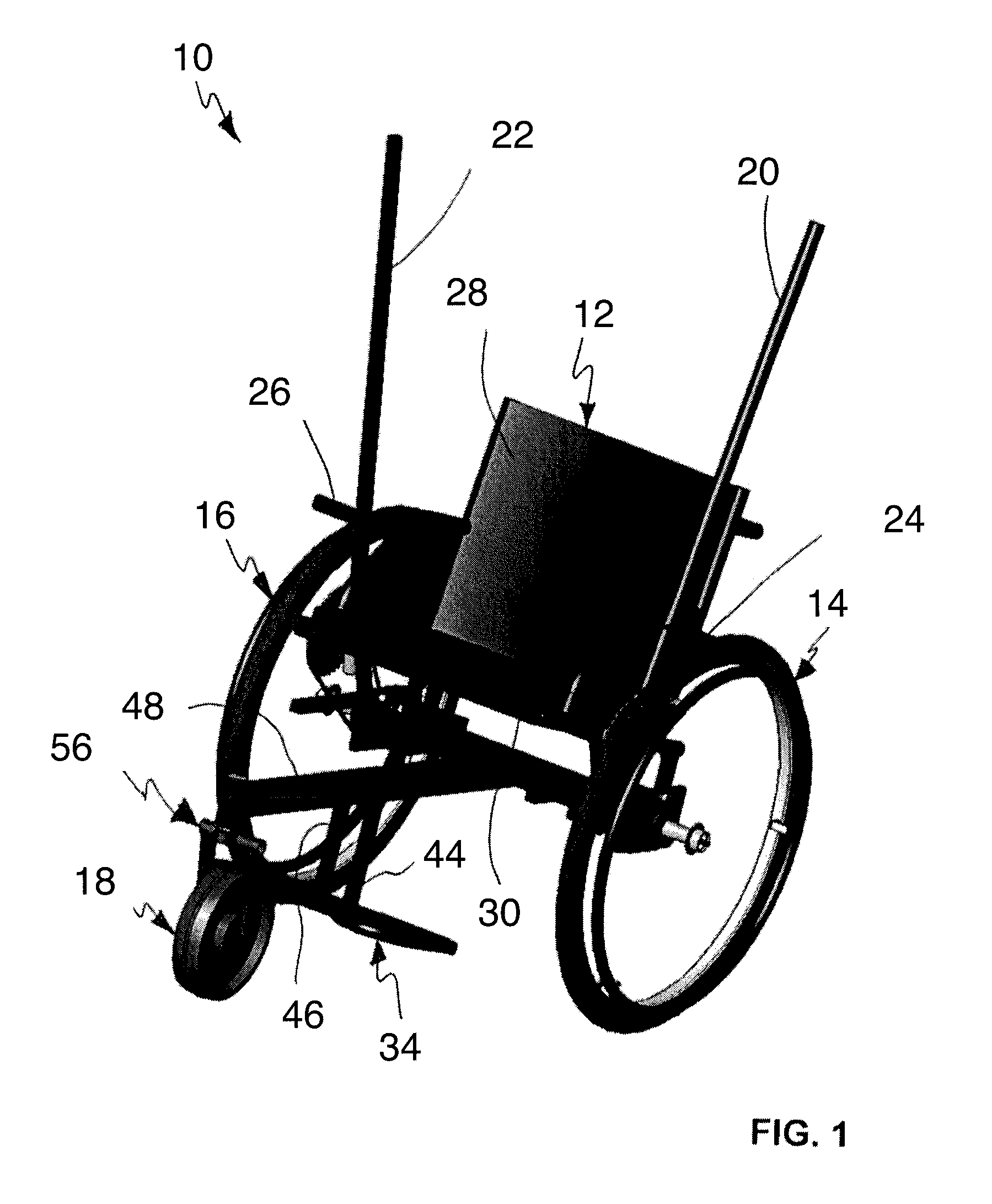
[0049]Turning to FIG. 1, an exemplary embodiment of a wheelchair 10 is shown. Wheelchair 10 has a seat 12, rear wheels 14, 16, and a front wheel 18. The drivetrain of wheelchair 10 includes a pair of levers 20, 22 for hand operation. Each lever 20, 22 includes a brake 24, 26, respectively, for frictionally engaging a wheel 14, 16, respectively. Although not shown, in an exemplary preferred embodiment, wheels 14, 16 may include spokes. Seat 12 may include a back portion 28 and a cushion portion 30 which may be disposed on a rigid plate 32 as shown in FIG. 7. A foot rest 34 for example may be formed of a pair of U-shaped tubes 36, 38 coupled to each other with a pair of cross-brace tubes 40, 42, as shown in FIG. 6. In alternate embodiments, tubes 36, 38 instead each may form a V-shape, an O-shape, a square or other rectangular shape, or another shape. Front and rear footrest standoffs 44, 46, respectively, couple cross-brace tubes 40, 42 to central member 48. Foot rest plates 50, 52 a...


PUM


Abstract

A manually powered wheelchair includes a first lever associated with a first rear wheel and demountably coupled to a first drivetrain, the first lever having a first brake thereon. The wheelchair also includes a second lever associated with a second rear wheel and demountably coupled to a second drivetrain, the second lever having a second brake thereon. Each drivetrain includes a chainring, a chain, and a freewheel, and each drivetrain has a fixed gear ratio. The freewheel of each drivetrain is actuated by manual pivoting of the lever associated therewith. In use, the wheelchair achieves changes in mechanical advantage when a user shifts the user's hands up and down the first and second levers.

Description

CROSS-REFERENCE TO RELATED APPLICATIONS[0001]This application is a continuation of U.S. patent application Ser. No. 12 / 914,986 filed Oct. 28, 2010 now abandoned and entitled “Wheelchair with Lever Drivetrain” and further claims the benefits of U.S. Provisional Application No. 61 / 255,848 filed Oct. 28, 2009 and entitled “Wheelchair with Lever Drivetrain” under 35 U.S.C. §119(e), and the entire contents of these applications are expressly incorporated herein by reference thereto.FIELD OF THE INVENTION[0002]The invention relates to a wheelchair. More particularly, the invention relates to a wheelchair with a lever drivetrain.BACKGROUND OF THE INVENTION[0003]In some areas of the world such as developing countries, there is a particular need for technology to assist in providing mobility to people with disabilities, regardless of their location, travel requirements, or local environment. It has been estimated, for example, that 20 million people in the developing world require a wheelcha...

Claims


Application Information

Patent Timeline
Patent Type & Authority Patents(United States)
IPC IPC(8): B62M1/16B62M3/00
CPCB62M3/00A61G5/023A61G5/025A61G5/1008A61G5/101A61G5/1018A61G5/1035A61G5/1075A61G2005/121A61G2005/128A61G5/121A61G5/128
Inventor WINTER, V, AMOS G.BOLLINI, MARIO A.DELATTE, DANIELLE M.O'HANLEY, HARRISON F.SCOLNIK, NATASHA K.JONES, GWYNDAF M.FREY, DANIEL D.JUDGE, BENJAMINGALLUP, BENJAMIN H.HICKS, DANIELLERULEMAN, NYDIACHEN, XUEFENG
Owner GLOBAL RES INNOVATION & TECH
Features
  • R&D
  • Intellectual Property
  • Life Sciences
  • Materials
  • Tech Scout
  • Unparalleled Data Quality
  • Higher Quality Content
  • 60% Fewer Hallucinations
Learn More