Self-locking bolt nut assembly

a self-locking, bolt-nut technology, applied in the direction of screws, fastening means, washers, etc., can solve the problems of deteriorating the reliability of the coupling portion, unable to withstand a high bolt coupling torque and compression force, and unable to withstand a severe environment, so as to prevent loosening, reliably continuously exhibit self-locking, and smooth tightening

Active Publication Date: 2014-09-30
LEE SANG CHEOL
View PDF17 Cites 13 Cited by
  • Summary
  • Abstract
  • Description
  • Claims
  • Application Information

AI Technical Summary

Benefits of technology

[0020]First, an object of the present invention is to provide a self-locking bolt-nut assembly in which a nut can be more smoothly tightened with elastic force of a washer, and after the tightening has been accomplished, the washer which is biased to return to its original state is elastically locked to the nut, so that the nut is prevented from becoming loose by vibrations or external force.
[0021]Second, another object of the present invention is to provide a self-locking bolt-nut assembly in which even if the nut is slightly loosened or is partially damaged after the tightening has been accomplished, the washer which has been in contact with the nut can reliably continuously exhibit the self-locking function.
[0022]Third, a further object of the present invention is to provide a self-locking bolt-nut assembly in which when a user rotates the nut to intentionally loosen the nut, the washer which is made of a thin plate is more easily broken than other elements, thus allowing the nut to be loosened, and the nut can be tightened to the bolt again with the self-locking function by replacing only the washer which is expendable with a new one.
[0023]Fourth, yet another object of the present invention is to provide a self-locking bolt-nut assembly which provides a means which can more precisely control and uniformly maintain the torque with which the nut is tightened.

Problems solved by technology

However, with the passage of time, such bolt-nut assemblies may gradually become loose because of external vibrations or shocks, thus deteriorating the reliability of the coupling portion.
1) The nut 3 and the washer 2 interact with each other in such a way that the washer 2 and the nut 3 pass over each other with compression strain therebetween rather than having the washer 2 elastically bend with respect to the nut 3 and then return to its original state. Thus, if the washer is made of a hard material, the one-way stop protrusions 3-2 of the nut 3 may not be able to pass over the one-way stop protrusions 2-3 of the washer 2.
Meanwhile, if the washer is made of soft material (for example, rubber, plastic, etc.), it cannot withstand a high bolt coupling torque and compression force.
Furthermore, it cannot withstand a severe environment, for example, high-temperature and high-pressure environment, for a long period of time.
Hence, the conventional bolt-nut structure cannot be used in a fastening element for a structure or power apparatus which is exposed to vibrations, shocks, high temperature conditions, etc.
3) Even if the nut 3 has been forcibly tightened on the bolt body 1, the one-way stop protrusions 2-3 and 3-2 of the washer 2 and the nut 3 are not completely brought into contact with each other or do not reliably lock into each other, thus causing the fastening to be unsatisfactory.
4) Therefore, after the nut 3 has been tightened onto the bolt body 1, the nut 3 is easily loosened despite comparatively low vibration, thereby making it difficult to keep a prescribed torque.
Thereby the tightening torque cannot be maintained constant.
6) In addition, once the nut 3 has been tightened on the bolt body 1, it is impossible to separate the nut 3 from the bolt to reuse it, thus wasting material.
7) When washers are manufactured, the amount of material required to form each washer is increased, and the shape of the washer is complex.
Thus, the production cost per unit is markedly increased.
8) The one-way stop protrusions 2-3 and 3-2 may be worn or damaged for various reasons, thus causing the nut 3 to become loose.
After this, there is no longer any means for preventing the nut from becoming loose.

Method used


Image

  • Self-locking bolt nut assembly
  • Self-locking bolt nut assembly
  • Self-locking bolt nut assembly

Examples


Embodiment Construction

[0045]Hereinafter, preferred embodiments of the present invention will be described in detail with reference to the accompanying drawings.

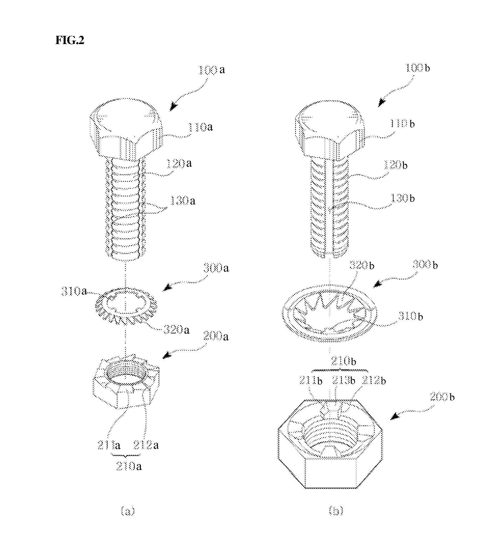
[0046]FIG. 2 is of perspective views showing a preferred embodiment of the present invention, in which FIG. 2a illustrates the case where elastic protrusions 320a are provided around a circumferential outer edge of a washer 300a, and FIG. 2b illustrates the case where elastic protrusions 320b are provided around a circumferential inner edge of a washer 300b.

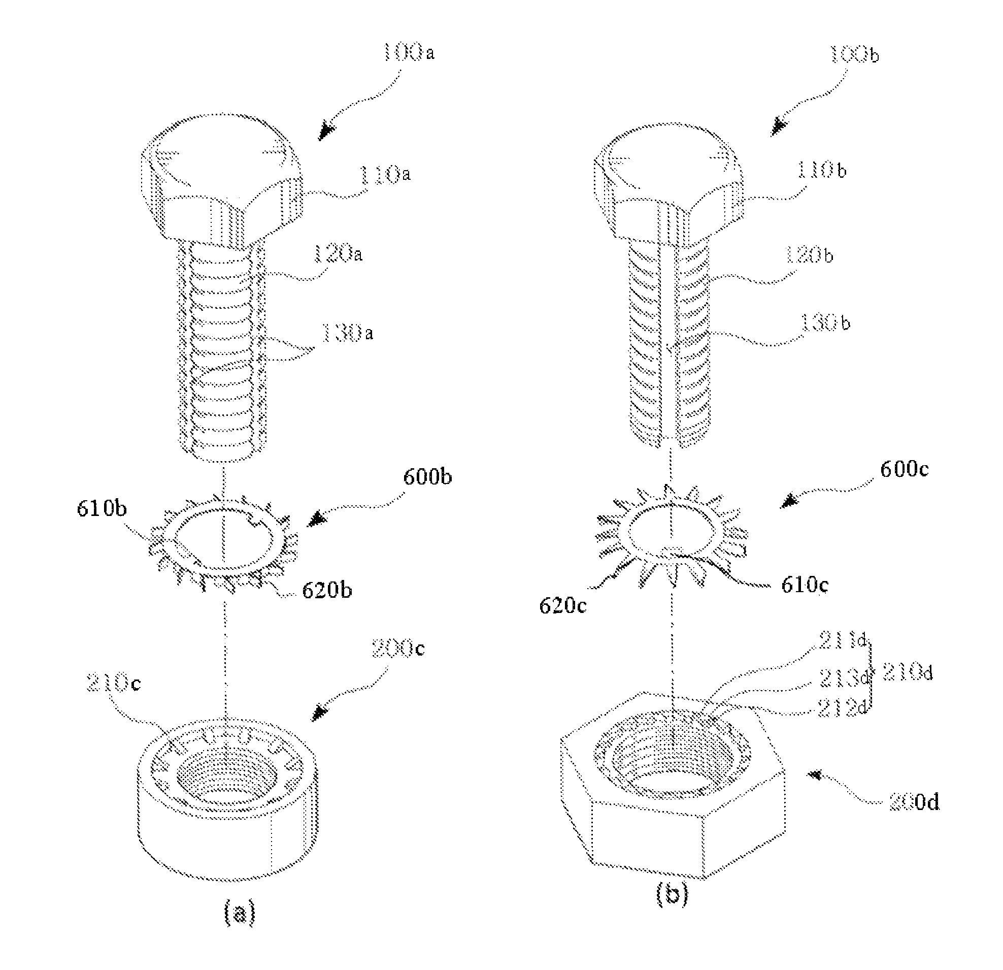
[0047]The bolt 100a includes a bolt head 110a and a bolt body 120a. An external thread is formed around the bolt body 120a, and an insertion guide groove 130a is formed in the bolt body 120a along the longitudinal direction of the bolt body 120a. The insertion guide groove 130a may be single or, alternatively, it may comprise a plurality of insertion guide grooves 130a.

[0048]The washer 300a includes a rotation-preventive protrusion 310a which protrudes from the circumferential inner edge of t...


PUM


Abstract

The present invention relates to a self-locking bolt-nut assembly including a bolt; a nut tightened on the bolt; and a washer provided between the bolt and the nut, wherein the nut has a counterbore being formed in the nut, and has a plurality of stop protrusions formed on the inner surface of the circumferential sidewall of the counterbored portion of the nut, the stop protrusions being arranged in a circumferential direction at regular intervals, the washer including the rotation-preventive protrusion protruded on inner circumference of the washer towards the center thereof, the rotation-preventive protrusion being inserted into the insertion guide groove; and a plurality of elastic protrusions which is protruded on outer circumference of the washer, being inclined in the direction where the nut is turned to tighten it.

Description

BACKGROUND OF THE INVENTION[0001](a) Field of the Invention[0002]The present invention relates to a bolt-nut assembly which includes a bolt, a nut and a washer and has a self-locking function that prevents the nut from becoming loose from the bolt.[0003](b) Description of the Related Art[0004]Typically, bolt-nut assemblies are widely used, in which a bolt is inserted through elements and a nut is then tightened on the bolt to fasten the elements to each other, in order to couple construction materials or mechanical elements to each other.[0005]However, with the passage of time, such bolt-nut assemblies may gradually become loose because of external vibrations or shocks, thus deteriorating the reliability of the coupling portion.[0006]In an effort to prevent a nut from becoming loose by reverse rotation of the nut, a variety of auxiliary fastening means have been proposed. A representative example of the auxiliary fastening means was disclosed in Korean Utility Model Registration No....

Claims


Application Information

Patent Timeline
Patent Type & Authority Patents(United States)
IPC IPC(8): F16B39/32F16B35/04F16B39/24F16B39/282F16B43/00
CPCF16B39/32F16B43/00F16B35/041F16B39/282F16B39/24Y10S411/953F16B39/02
Inventor LEE, SANG, CHEOL
Owner LEE SANG CHEOL
Why Eureka
Try Eureka