Screw compressor

a screw compressor and compressor technology, applied in the direction of machines/engines, rotary/oscillating piston pump components, liquid fuel engines, etc., can solve the problems of insufficient thickness of passages and other parts formed by casting, insufficient spread of molten metal, and inability to achieve desired shape, etc., to achieve convenient secure

Active Publication Date: 2014-09-30
KOBE STEEL LTD
View PDF22 Cites 3 Cited by
  • Summary
  • Abstract
  • Description
  • Claims
  • Application Information

AI Technical Summary

Benefits of technology

[0011]According to this configuration, since a pipe member for feeding fluid to the inside interior space is a member that is separate from a casing main body, the pipe member can be made of a thin material, and the screw compressor is easily made smaller and more light-weight.
[0013]According to this configuration, since there is some degree of freedom-in fixation of the flange to the outer wall using the gasket, concentric misalignment between the fitting hole of the internal dividing wall and the through hole of the outer wall can be absorbed, and air-tightness of the inside interior space and the outside interior space can be easily secured. In addition, since welding or the like is not needed to fix the communication pipe member to the casing, strain or the like is not caused by heat, and cracks are thus less likely to be generated.

Problems solved by technology

However, since screw compressors are designed according to various demands, in some screw compressors, the internal portion of the casing and the outer wall portion thereof are not necessarily connected in the radial direction in terms of strength.
Although passages and other parts are formed only for passage of a small amount of fluid, passages and other parts that are formed by the casting may not have sufficient thickness in some cases.
In these cases, molten metal may not sufficiently spread and may not become desired shape.
As a result, the formed passages may communicate with other interior spaces due to insufficient wall thickness.
In addition, since the cooling speed becomes uneven, material defects may be caused, resulting in breakage.
Thus, the casing becomes heavy and large.

Method used


Image

  • Screw compressor
  • Screw compressor
  • Screw compressor

Examples


Embodiment Construction

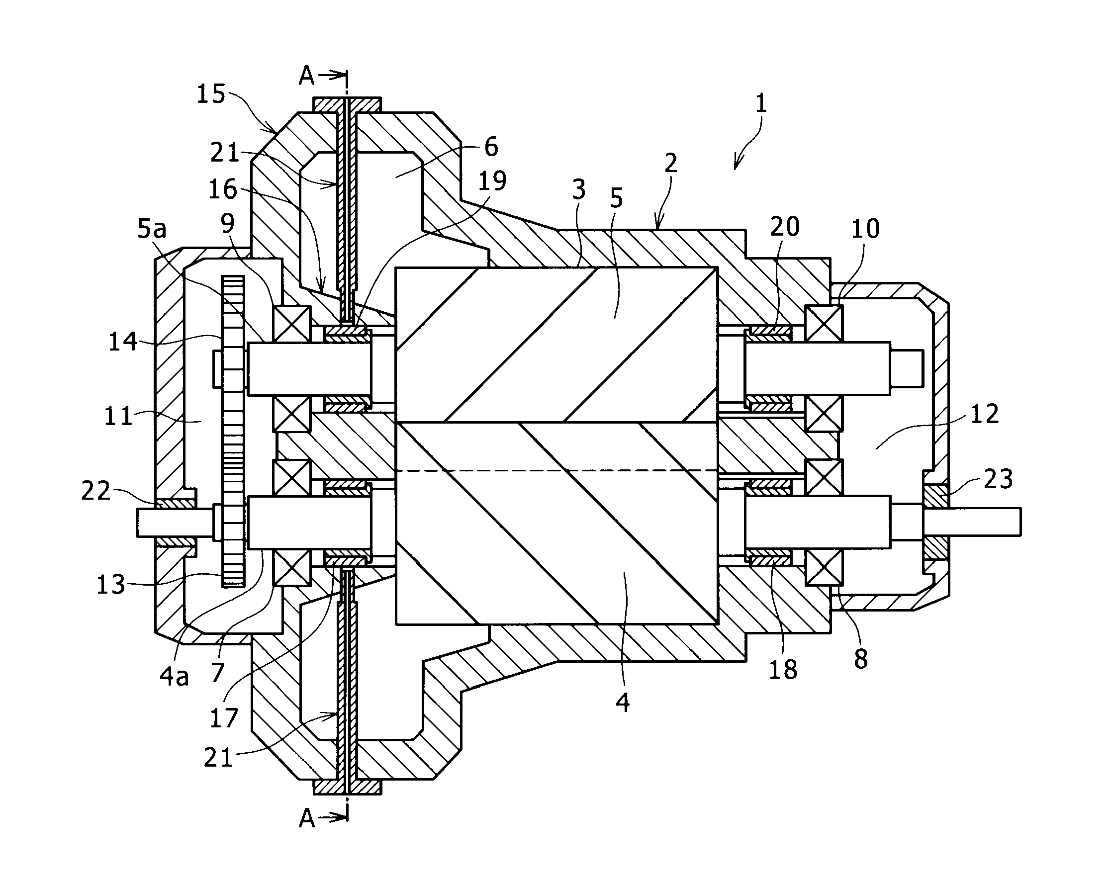
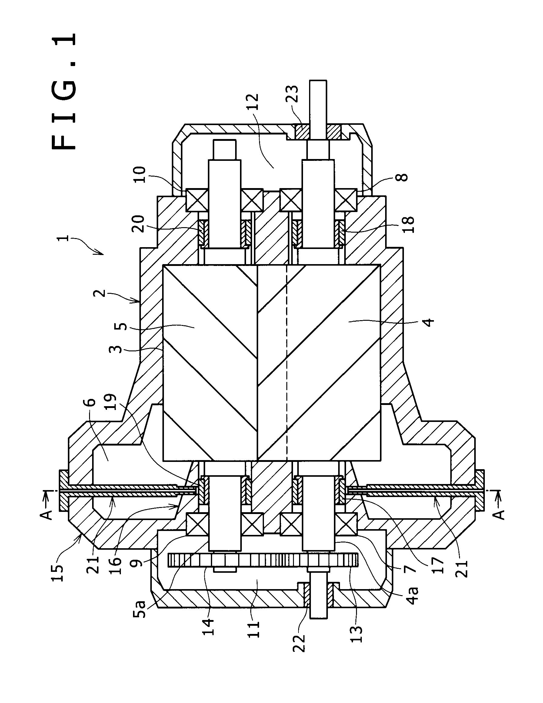
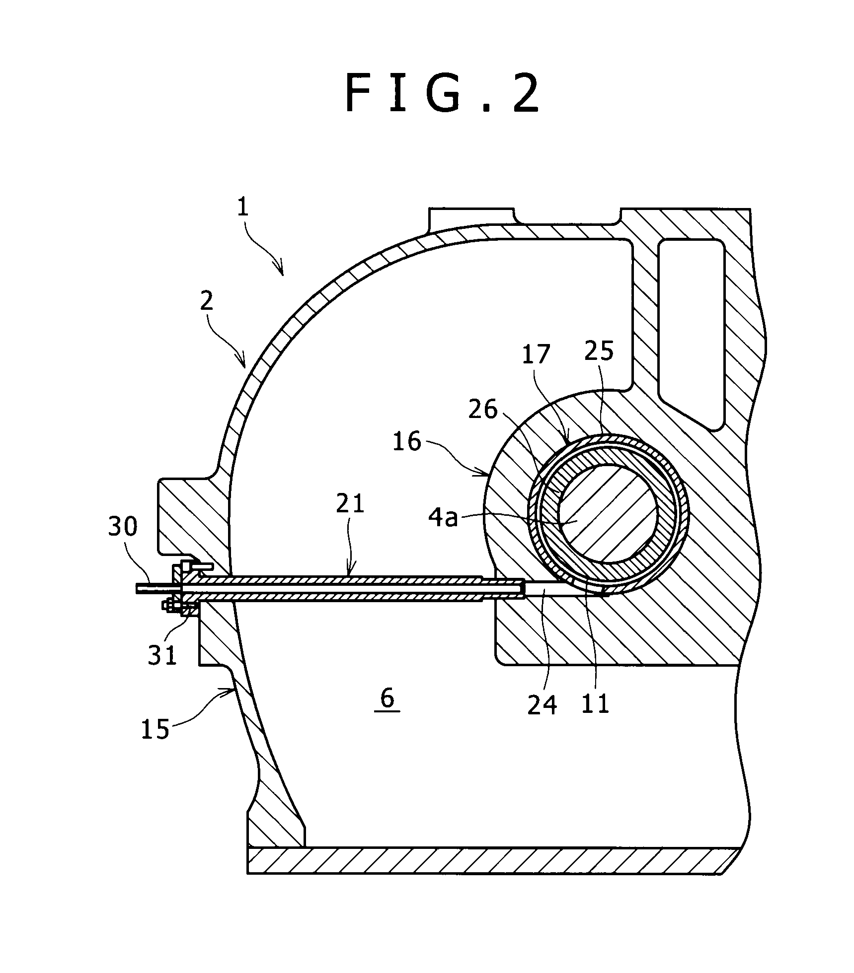
[0019]A screw compressor of an embodiment of the present invention is now described with reference to accompanying drawings. FIG. 1 shows a cross-section of the whole of a compressor 1 of a first embodiment of the present invention along the shaft of the screw rotor thereof. FIG. 2 shows a cross-section along the line A-A of FIG. 1, i.e., a partial cross-section of the screw compressor 1 along a direction perpendicular to the shaft.

[0020]The screw compressor 1 of the present embodiment accommodates a pair of rotatable male and female screw rotors (male rotor 4 and female rotor 5) in a compression chamber 3 formed in a casing 2 composed of a casting. The casing 2 defines a suction space (outside interior space) 6 that communicates with the compression chamber 3 and to which a suction pipe (not shown) is connected, and bearing spaces (inside interior spaces) 11 and 12 that accommodate bearings 7 to 10 that support shafts 4a and 5a of the screw rotors 4 and 5. The suction-side bearing ...


PUM


Abstract

Provided is a screw compressor, accommodating a pair of rotatable male and female screw rotors in a compression chamber formed in a casing, wherein the casing includes: an internal dividing wall that defines an inside interior space; and an outer wall that defines an outside interior space arranged outside the inside interior space The screw compressor further includes: a communication pipe member that penetrates the outer wall and extends across the outside interior space, and an end of the communication pipe member being inserted into the internal dividing wall so that the inside interior space communicates with a passage outside the outer wall. By using this communication pipe member, fluid can pass across an interior space in the casing to be fed to another interior space formed further inside.

Description

BACKGROUND OF THE INVENTION[0001]1. Field of the Invention[0002]The present invention relates to a screw compressor.[0003]2. Description of the Related Art[0004]A screw compressor that accommodates a pair of male and female rotors in a compression chamber (rotor chamber) formed in a casing, and that compresses gas drawn from a suction passage by the rotation of the rotors and discharges the compressed gas from a discharge passage is widely used.[0005]Bearings that support rotor shafts of a pair of male and female screw rotors, and shaft sealing members disposed around the rotor shafts to isolate a compression chamber from the other space are necessarily provided for a screw compressor. The bearings are generally fed with lubrication oil. When non-contacting sealing such as dry gas seal is used for shaft sealing parts, so-called seal gas needs to be fed to the shaft sealing parts in many cases. In addition, fluid (e.g., air) compression may generate so-called drain. Therefore, in man...

Claims


Application Information

Patent Timeline
Patent Type & Authority Patents(United States)
IPC IPC(8): F01C1/16F04C18/08F04C18/16F04C29/02
CPCF04C18/16F04C29/028F04C18/086F04C2240/806
Inventor TAKAKI, SHUGO
Owner KOBE STEEL LTD
Why Eureka
Try Eureka