Electrophotographic member, process cartridge and electrophotographic apparatus

a technology of electrophotography and process cartridges, applied in the direction of electrographic process apparatus, thin material processing, instruments, etc., can solve the problems of surface layer deformation recovery properties under high temperature and high humidity, and achieve the effect of high durability and high quality

Active Publication Date: 2014-09-30
CANON KK
View PDF14 Cites 33 Cited by
  • Summary
  • Abstract
  • Description
  • Claims
  • Application Information

AI Technical Summary

Benefits of technology

[0010]In recent years, an electrophotographic apparatus is demanded for being capable of maintaining high quality and high durability even under a more stringent environment.
[0013]The present invention is directed to providing an electrophotographic member that is excellent in deformation recovery property even if being stored and used under a high-temperature and high-humidity environment and also excellent in filming resistance under low-temperature and low-humidity, and that serves to form a high quality electrophotographic image.
[0014]Further, the present invention is directed to providing an electrophotographic image forming apparatus that can stably output a high quality electrophotographic image, and a process cartridge for use in the apparatus.
[0015]The present inventors have intensively studied in order to achieve the above objects. As a result, the present inventors have found that a surface layer containing a polyurethane resin having a particular structure is excellent in deformation recovery during storage under a high-temperature and high-humidity environment for a long period, is flexible under a low-temperature and low-humidity environment, and can suppress filming at a high level, thereby leading to the present invention.
[0033]By providing a surface layer containing a urethane resin having a particular structural unit and a crosslinked structure on an elastic layer, the present invention achieves an electrophotographic member that is excellent in deformation recovery during storage under a high-temperature and high-humidity environment for a long period and enables filming to be suppressed under a low-temperature and low-humidity environment at a high level, serving to form a high quality electrophotographic image.
[0034]The present invention can also achieve a process cartridge and an electrophotographic apparatus that enable a high quality electrophotographic image to be stably formed.

Problems solved by technology

By the way, while a surface layer made of a flexible urethane resin is excellent in suppression of fusion (filming) of a toner under low-temperature and low-humidity, the surface layer may have a problem of deformation recovery property under high-temperature and high-humidity because of being flexible.

Method used


Image

  • Electrophotographic member, process cartridge and electrophotographic apparatus
  • Electrophotographic member, process cartridge and electrophotographic apparatus
  • Electrophotographic member, process cartridge and electrophotographic apparatus

Examples


example 1

[0196]Hereinafter, a method for manufacturing the electrophotographic member of the invention of the present application will be described.

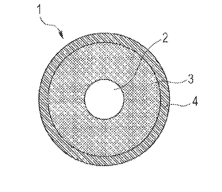
[0197]As materials for the surface layer 4, 43.9 parts by mass of the amino compound C-1, 108.0 parts by mass of carbon black (trade name, MA230; produced by Mitsubishi Chemical Corporation), and 90.0 parts by mass of urethane resin fine particles (trade name, Art Pearl C-400; produced by Negami Chemical Industrial Co., Ltd.) were mixed with 794.3 parts by mass of the isocyanate group terminal prepolymer B-1 under stirring.

[0198]Then, methyl ethyl ketone (hereinafter MEK) was added thereto so that the total solid content ratio was 30% by mass, and then mixed by a sand mill. Then, the resultant was further adjusted by MEK so as to have a viscosity of 10 to 13 cps, to prepare a coating material for forming a surface layer.

[0199]The elastic roller D-1 produced in advance was dipped in the coating material for forming a surface layer to form a coatin...

examples 2 to 39

[0219]Coating materials for forming a surface layer were produced in the same manner as in Example 1 except that materials shown in the following Table 5 were used as materials for the surface layer 4. Then, each of the coating materials was applied to the elastic roller D-1, dried and heated to produce a developer carrying member of each of Examples 2 to 39, in the same manner as in Example 1.

[0220]

TABLE 5Isocyanate groupCompound of structuralterminal prepolymerformula (8)Part(s)Part(s)ExampleNo.by massNo.by mass1B-1794.3C-143.92705.0C-2106.53695.3C-3113.34656.8C-4140.35785.5C-550.26768.2C-662.37792.3C-745.48696.0C-8112.89761.1C-967.210736.5C-1084.511770.6C-1160.612745.4C-1278.213723.8C-1393.414651.3C-14144.115688.0C-15118.416574.7C-16197.717793.3C-1744.718790.6C-1846.619705.0C-19106.520695.3C-20113.321563.8C-21205.422B-2761.1C-967223B-3785.350.324B-4785.350.325B-5779.954.026748.9C-1375.827B-6779.9C-954.028B-7783.451.629B-8785.350.330B-9776.556.531B-10779.954.032B-11785.350.333B-12...


PUM


Abstract

A high quality electrophotographic member that is excellent in deformation recovery property under high-temperature and high-humidity and that also satisfies filming resistance under low-temperature and low-humidity is provided.The electrophotographic member includes a substrate, an elastic layer, and a surface layer containing a urethane resin, wherein the urethane resin has a partial structure having at least one structure selected from the group consisting of structures of structural formulae (1) to (7) between adjacent two urethane linkages, and the urethane resin further has a partial structure derived from a reaction of a compound represented by a structural formula (8) with a polyisocyanate.

Description

CROSS-REFERENCE TO RELATED APPLICATIONS[0001]This application is a continuation of International Application No. PCT / JP2013 / 003806, filed Jun. 19, 2013, which claims the benefit of Japanese Patent Applications No. 2012-144348, filed Jun. 27, 2012 and No. 2013-126827, filed Jun. 17, 2013.BACKGROUND OF THE INVENTION[0002]1. Field of the Invention[0003]The present invention relates to an electrophotographic member for use in an electrophotographic apparatus, and a process cartridge and an electrophotographic apparatus having the electrophotographic member.[0004]2. Description of the Related Art[0005]In an electrophotographic apparatus (for example, a copier, a facsimile, and a printer using an electrophotographic system), an electrophotographic photosensitive member (hereinafter, also referred to as “photosensitive member”) is charged by a charging unit and exposed by laser or the like, and as a result, an electrostatic latent image is formed on the photosensitive member. Then, a toner...

Claims


Application Information

Patent Timeline
Patent Type & Authority Patents(United States)
IPC IPC(8): G03G15/08
CPCY10T428/31598G03G15/75G03G15/0818G03G15/06Y10T428/31551G03G15/0808G03G21/18G03G15/0216
Inventor YAMADA, MASAKIISHIDA, KAZUTOSHIITO, MINORUWAKABAYASHI, KAZUHITOUESUGI, TOMOYA
Owner CANON KK
Why Eureka
Try Eureka