Operation amount detection apparatus

a detection apparatus and amount technology, applied in the direction of instruments, mechanical control devices, apparatus for force/torque/work measurement, etc., can solve the problem of excessive deflection of the transmission member, and achieve the effect of reducing strength, increasing the amount of deflection of the connecting portion, and securing the strength of the transmission member

Active Publication Date: 2014-10-07
TOYOTA JIDOSHA KK +1
View PDF21 Cites 9 Cited by
  • Summary
  • Abstract
  • Description
  • Claims
  • Application Information

AI Technical Summary

Benefits of technology

[0007]The invention provides an operation amount detection apparatus capable of both securing strength of a transmission member that transmits a load corresponding to an operation amount and inhibiting the transmission member from becoming excessively large.
[0022]In the above configuration, when deflection in which the relative displacement becomes a prescribed amount occurs in the connecting portions, the connecting portions may further transmit a load without going through the transmission member by causing the shaft portion side and the operation target member side to make contact.
[0023]The operation amount detection apparatus in an aspect of the invention has a connecting portion that connects a first support portion supported by an operation target member and a second support portion supported by a shaft portion. The first support portion and the second support portion are arranged at different locations in the lengthwise direction of the shaft portion. A plurality of connecting portions are provided in parallel between the first support portion and the second support portion, and deflect by transmission of a load so that the first support portion and the second support are relatively displaced. Each connecting portion is mutually opposed in a direction perpendicular to the lengthwise direction of the shaft portion. As a result, a load that acts on each of the connecting portions after being dispersed decreases, thereby making it possible to reduce strength and increase the amount of deflection of the connecting portions. Accordingly, the effect is demonstrated by which securing of strength for the transmission member and inhibiting excessive increases in size of the transmission member can both be realized.

Problems solved by technology

However, when the amount of deformation of the transmission member is attempted to be increased while maintaining the strength thereof, there is the problem of this causing the transmission member to become excessively large.

Method used


Image

  • Operation amount detection apparatus
  • Operation amount detection apparatus
  • Operation amount detection apparatus

Examples


first example

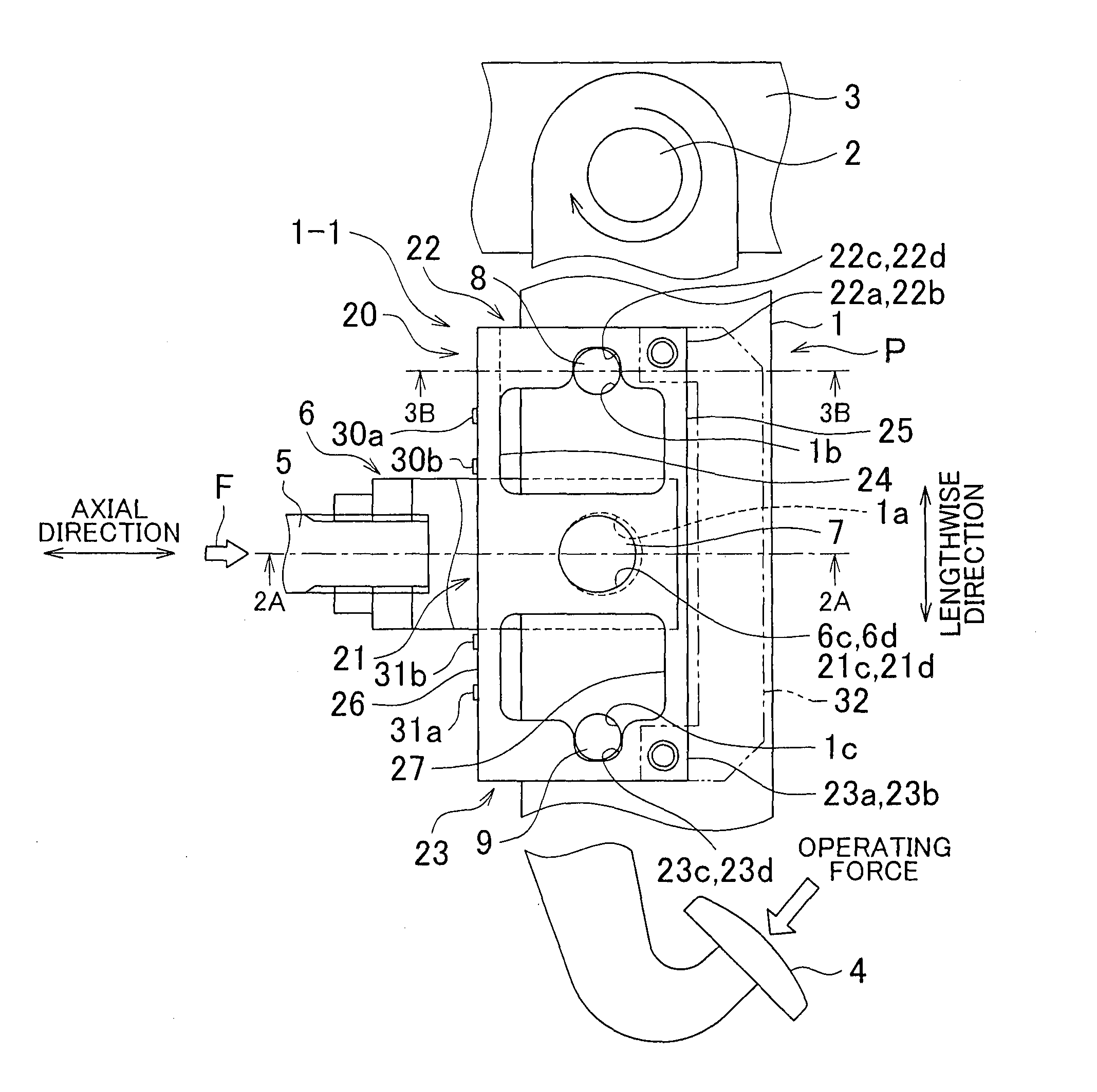
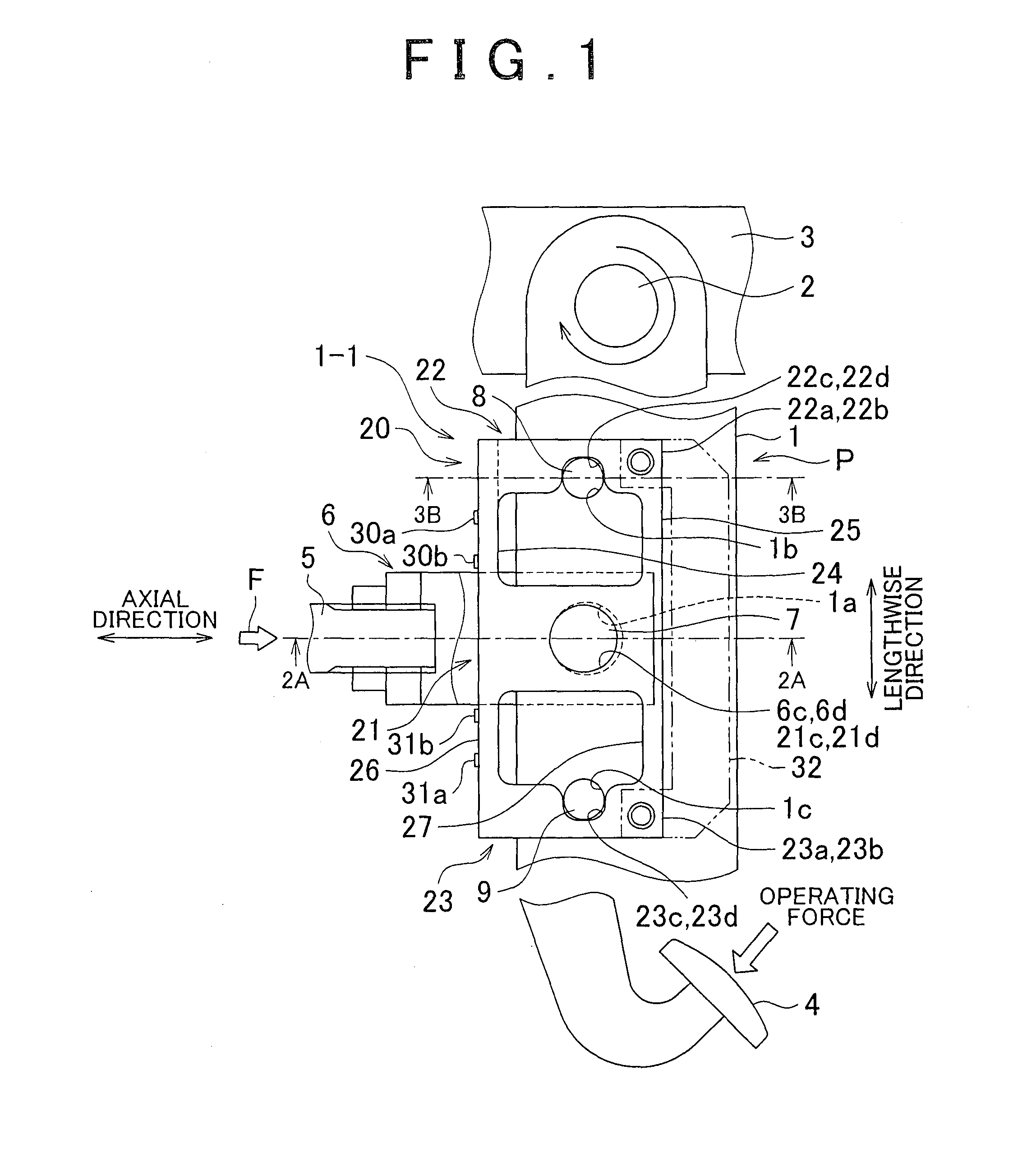
[0040]The following provides an explanation of a first example with reference to FIGS. 1 to 3. The first example relates to an operation amount detection apparatus that detects an operation amount transmitted from an operation member to an operation target member. FIG. 1 is a front view of an essential portion in which a portion representing the operation amount detection apparatus relating to the first example of the invention has been cut away. FIG. 2 is a cross-sectional view taken along line 2A-2A of FIG. 1 showing the structure of a first support portion of the operation amount detection apparatus of the first example, and FIG. 3 is a cross-sectional view taken along line 3B-3B of FIG. 1 showing the structure of a second support portion of the operation amount detection apparatus of the first example.

[0041]A pedal arm (shaft portion) 1 of a brake pedal (operation member) P provided in a vehicle not shown is shown in FIG. 1. A rotating shaft 2, which is provided on one end in th...

second example

[0060]The following provides an explanation of a second example with reference to FIGS. 4A and 4B. The same reference symbols are used to indicate those members of the second example that have the same functions as those explained in the above-mentioned example, and duplicate explanations thereof are omitted. FIGS. 4A and 4B are a front view and cross-sectional view of an essential portion in which a portion has been cut away representing an operation amount detection apparatus 1-2 of the second example.

[0061]In a transmission member 40 of the second example, connecting portions 45 (45a, 45b) to which strain sensors 50 (50a, 50b) are attached and connecting portions 44 (44a, 44b) provided in parallel to the connecting portions 45 are beams having equal amounts of deformation, and are arranged in the shape of parallel link. As a result, the direction and amount of deformation of the connecting portions 45 are stabilized and detection accuracy of an operation amount is improved.

[0062]...

third example

[0070]The following provides an explanation of a third example with reference to FIGS. 5A and 5B. The same reference symbols are used to indicate those members of the third example that have the same functions as those explained in the above-mentioned examples, and duplicate explanations thereof are omitted. FIGS. 5A and 5B are a front view and cross-sectional view of an essential portion in which a portion has been cut away representing an operation amount detection apparatus 1-3 of the third example.

[0071]In a transmission member 60 of the third example, a configuration is employed in which a first support portion 61 and either of a second support portion 62 or 63 consist of a pair of mutually independent plate portions. As a result, the transmission member 60 can be formed of two independent plate members, thereby making it possible to realize compact size, improved moldability and reduced costs by virtue of reducing the space required by the transmission member 60.

[0072]Similar ...


PUM

PropertyMeasurementUnit
transmissionaaaaaaaaaa
relative displacementaaaaaaaaaa
operating forceaaaaaaaaaa

Abstract

An operation amount detection apparatus includes a transmission member that transmits a load corresponding to an operation amount between a shaft portion and an operation target member through connecting portions that connect a first support portion supported by the operation target member and a second support portion supported by the shaft portion, and a detection device that detects an operation amount based on an amount of deformation of the connecting portions. A plurality of the connecting portions are provided in parallel between the first support portion and the second support portion, and deflect due to transmission of a load so that the first support portion and the second support are relatively displaced in a direction of a linear motion. The respective connecting portions are mutually opposed in a direction perpendicular to a lengthwise direction of the shaft portion.

Description

BACKGROUND OF THE INVENTION[0001]1. Field of the Invention[0002]The invention relates to an operation amount detection apparatus.[0003]2. Description of the Related Art[0004]An operation amount detection apparatus is available in the related art that detects an operation amount based on an amount of deformation of a transmission member that transmits a load corresponding to an operation amount between an operation member such as a pedal and an operation target member.[0005]For example, Japanese Patent Application Publication No. 2000-103325 (JP-A-2000-103325) discloses an operation amount detection apparatus provided with a base member that transmits a brake operating force, a booster-side operating rod that receives the operating force, and a rod-like member connected to the base member and the booster-side operating rod. In this operation amount detection apparatus, a technology is disclosed in which, in the case an operating force is applied, strain caused by bending generated in...

Claims


Application Information

Patent Timeline
Patent Type & Authority Patents(United States)
IPC IPC(8): G01L1/04B60T7/04B60T11/18G01L5/00G01L5/22G05G1/46
CPCG01L5/0038G01L5/225B60T11/18B60T7/042G05G1/46G01L1/04
Inventor ISONO, HIROSHIFUJIWARA, NOBORUOTSUKA, HIROFUMI
Owner TOYOTA JIDOSHA KK
Why Eureka
Try Eureka