Low-voltage detection circuit

Active Publication Date: 2006-07-13
WINBOND ELECTRONICS CORP
View PDF10 Cites 5 Cited by
  • Summary
  • Abstract
  • Description
  • Claims
  • Application Information

AI Technical Summary

Benefits of technology

[0023] In the present invention, the MOS transistor of the to-be-tested circuit is used to measure the minimum operational voltage of the to-be-tested circuit. Without the influence of the fabricating process of the MOS transistor, the present invention can improve the utility rate of the battery. In ad

Problems solved by technology

However, the power capacity of batteries is limited.
As a result, the to-be-te

Method used


Image

  • Low-voltage detection circuit
  • Low-voltage detection circuit
  • Low-voltage detection circuit

Examples


Embodiment Construction

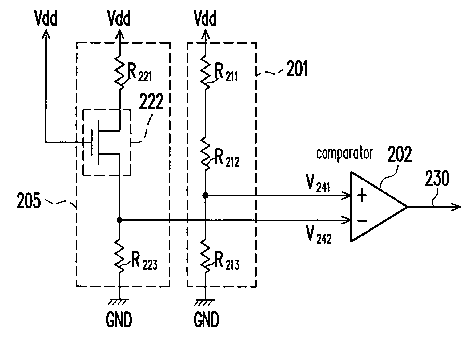
[0027] The reference power source of the conventional low-voltage detection circuit has a specific operational voltage and the low-voltage detection circuit cannot operate under a voltage lower than that. With the fabricating process of the metal-oxide-semiconductor (MOS) transistor, though some integrated circuits can operate normally under a low voltage, the specific reference voltage would waste the power of the battery. Accordingly, the present invention uses the MOS transistor of the to-be-tested integrated circuit to test the operational voltage. The minimum operational voltage of each circuit can be determined based on the fabrication process. Thus, the efficiency of the battery can be improved. Without a specific operational voltage, the detection circuit of the present invention and the to-be-tested integrated circuit can both operate under the minimum operational voltage.

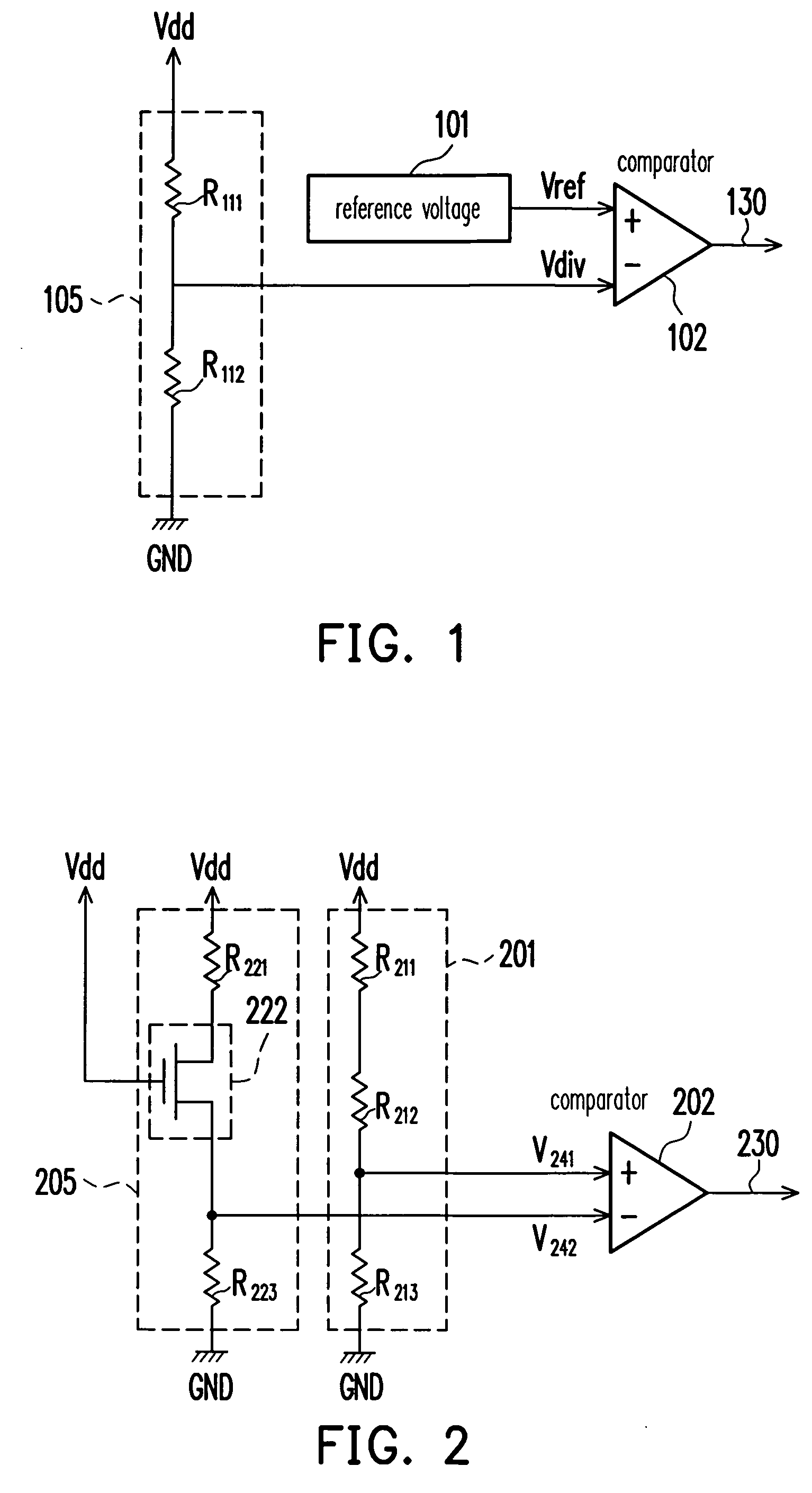
[0028] The following is an embodiment of the present invention. FIG. 2 is a schematic circuit drawing ...


PUM


Abstract

A low-voltage detection circuit detects a terminal voltage of a power supply terminal. The low-voltage detection circuit includes a first voltage-dividing circuit, a second voltage-dividing circuit, and a comparator. The second voltage-dividing circuit includes a bias circuit and a metal-oxide-semiconductor (MOS) transistor. The comparator compares and receives a voltage generated by the first voltage-dividing circuit and a voltage generated by the second voltage-dividing circuit to generate a voltage detection signal.

Description

CROSS-REFERENCE TO RELATED APPLICATION [0001] This application claims the priority benefit of Taiwan application serial no. 94100438, filed on Jan. 7, 2005. All disclosure of the Taiwan application is incorporated herein by reference. BACKGROUND OF THE INVENTION [0002] 1. Field of the Invention [0003] The present invention relates to a voltage detection circuit, and more particularly to a low-voltage detection circuit capable of precisely measuring a voltage. [0004] 2. Description of the Related Art [0005] With the advance of technology, hand-held electronic apparatuses, such as electronic dictionaries, cellular phones, walkmans, or digital cameras, which are driven by low voltages, have become commonplace in our daily lives. The power of integrated circuits of the electronic apparatus is supplied by batteries. However, the power capacity of batteries is limited. Therefore, users must pay attention as to when the power is running out and when the battery needs to be replaced or char...

Claims


Application Information

Patent Timeline
IPC IPC(8): H03K5/22
CPCG01R19/16542
Inventor WU, LI-TE
Owner WINBOND ELECTRONICS CORP
Why Eureka
Try Eureka