AC-to-DC power converting device

a power conversion device and converting device technology, applied in the field of ac-to-dc power conversion devices, can solve the problems of increasing power consumption of the industry, a relatively large volume, and inability to achieve zero-voltage switching of the second and third switches, etc., to achieve the effect of eliminating high-frequency nois

Inactive Publication Date: 2014-10-07
I-SHOU UNIVERSITY
View PDF10 Cites 37 Cited by
  • Summary
  • Abstract
  • Description
  • Claims
  • Application Information

AI Technical Summary

Benefits of technology

[0015]Therefore, an object of the present invention is to provide a power converting device that can overcome the aforesaid drawbacks of the prior art.
[0017]a filter adapted to be coupled to the external power source for filtering the AC input voltage therefrom to eliminate high-frequency noises;

Problems solved by technology

1. The first switch 121 of the power factor corrector 12 is required to have a high endurance voltage such that a relatively large conducting impedance is exhibited by the first switch 121.
2. A relatively large current flows through the inductor (L) of the power factor corrector 12. Therefore, the inductor (L) has increased power consumption, and a relatively large volume.
3. There are three switches 121, 122, 123 required in the conventional power converting device.
4. Zero-voltage switching characteristics of the second and third switches 122, 123 are associated with the load. When the load is extremely small, an extremely small resonant current generated in the power factor corrector 12 to flow through the second and third switches 122, 123 cannot eliminate energy stored in parasitic capacitances of the second and third switches 122, 123. Therefore, zero-voltage switching of the second and third switches 122, 123 cannot be attained.

Method used


Image

  • AC-to-DC power converting device
  • AC-to-DC power converting device
  • AC-to-DC power converting device

Examples


Embodiment Construction

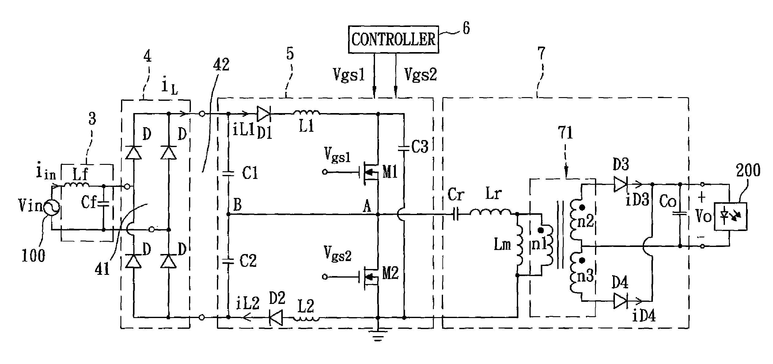
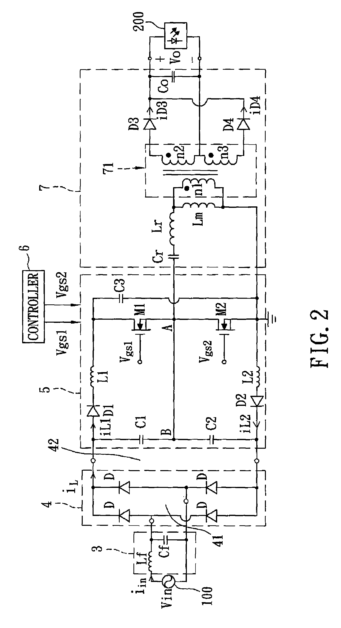
[0043]Referring to FIG. 2, the preferred embodiment of a power converting device according to the present invention is shown to be adapted for converting an AC input voltage (vin) supplied by an external power source 100 to a DC output voltage (Vo). The DC output voltage (Vo) is used to drive an LED module 200 that serves as a load. The power converting device includes a filter 3, a full-bridge rectifier 4, a power factor corrector 5, a controller 6, and a step-down converter 7.

[0044]The filter 3 includes an input inductor (Lf) and an input capacitor (Cf) connected in series, and is adapted to be coupled to the external power source 100 for filtering the AC input voltage (vin) therefrom to eliminate high-frequency noises and electromagnetic interference.

[0045]The rectifier 4 includes four diodes (D), and has an input side 41 coupled across the capacitor (Cf) of the filter 3 for receiving the AC input voltage (vin) filtered by the filter 3, and an output side 42. The rectifier 4 rect...


PUM


Abstract

An AC-to-DC power converting device includes: a filter for filtering an external AC input voltage; a rectifier for rectifying the AC input voltage filtered by the filter to output a rectified voltage; a power factor corrector for receiving the rectified voltage from the rectifier to generate a boosted voltage; and a step-down converter for receiving the boosted voltage from the power factor corrector to output a DC output voltage. The power factor corrector includes first and second capacitors connected in series across an output side of the rectifier, a series connection of a first diode, a first inductor, a third capacitor, a second inductor and a second diode coupled to the output side of the rectifier, and first and second switches connected in series across the third capacitor. A common node between the first and second capacitors is coupled to a common node between the first and second switches.

Description

CROSS-REFERENCE TO RELATED APPLICATION[0001]This application claims priority of Taiwanese Application No. 099121219, filed on Jun. 29, 2010.BACKGROUND OF THE INVENTION[0002]1. Field of the Invention[0003]The invention relates to a power converting device, and more particularly to an AC-to-DC power converting device.[0004]2. Description of the Related Art[0005]FIG. 1 illustrates a conventional power converting device for converting an AC input voltage (vi) supplied by an external power source 100′ to a DC output voltage (Vo) that is adapted for driving an LED module 200′ that serves as a load. The conventional power converting device includes a filter 10, a full-bridge rectifier 11, a power factor corrector 12, and a step-down converter 13.[0006]The filter 10 is coupled to the external power source 100′, and receives the AC input voltage (vi) for filtering the AC input voltage (vi) to eliminate electromagnetic interference.[0007]The full-bridge rectifier 11 has an input side coupled ...

Claims


Application Information

Patent Timeline
Patent Type & Authority Patents(United States)
IPC IPC(8): H02M3/335G05F5/00H02M1/42
CPCH02M1/4258H02M1/4241Y02B70/126Y02B70/10
Inventor CHENG, CHUN-ANYEN, CHUN-HSIENLIN, KUN-JHENG
Owner I-SHOU UNIVERSITY
Why Eureka
Try Eureka