Leg-portion attachment structure and image forming apparatus provided therewith
a technology of attachment structure and image forming apparatus, which is applied in the direction of washstands, furniture parts, revolving cabinets, etc., can solve the problems of increasing the cost of the apparatus, increasing high cost of the wheels, so as to reduce the load of the apparatus main body, stabilize the apparatus main body, and support the load of the apparatus
- Summary
- Abstract
- Description
- Claims
- Application Information
AI Technical Summary
Benefits of technology
Problems solved by technology
Method used
Image
Examples
first embodiment
[0055](First Embodiment)
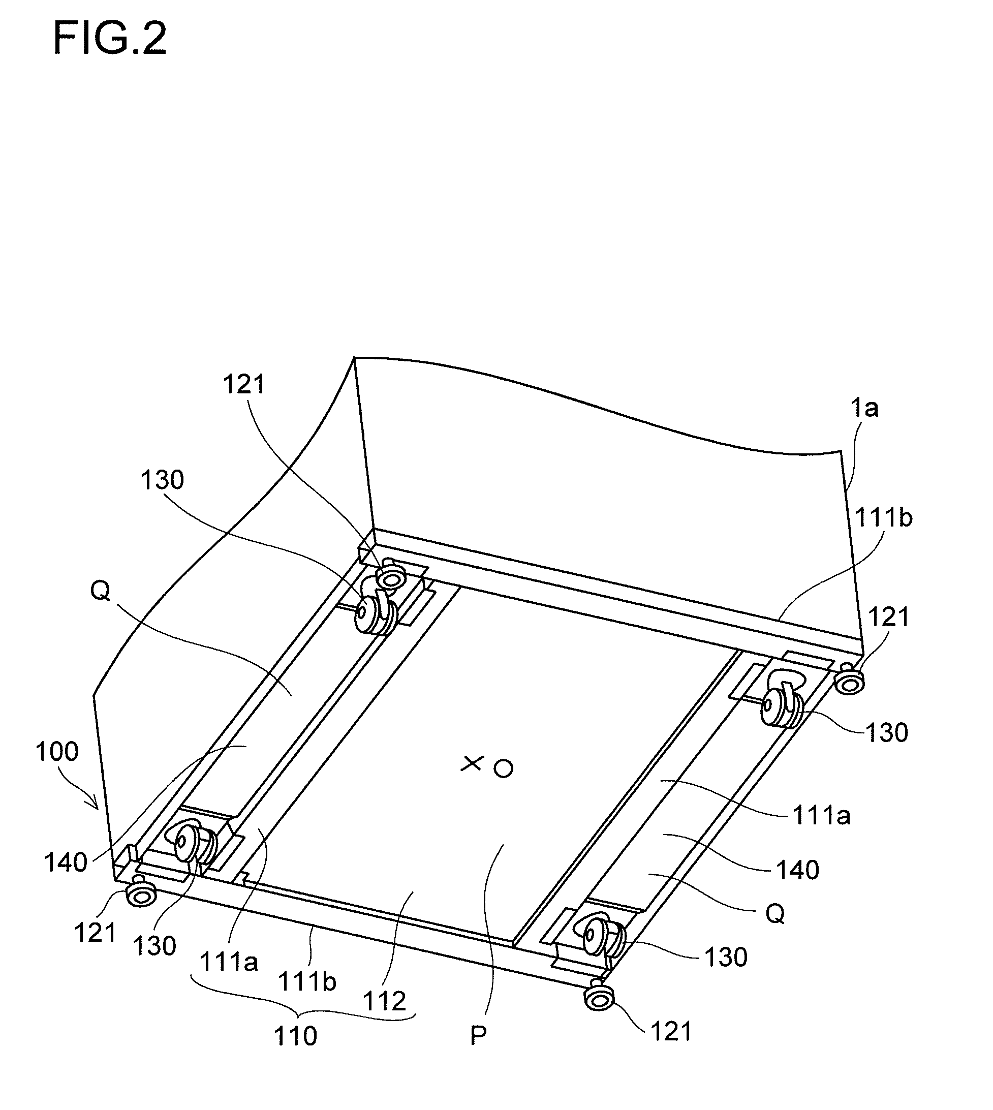
[0056]FIG. 2 is a perspective view from a floor surface side, illustrating the leg-portion attachment structure 100 according to a first embodiment of the present invention.
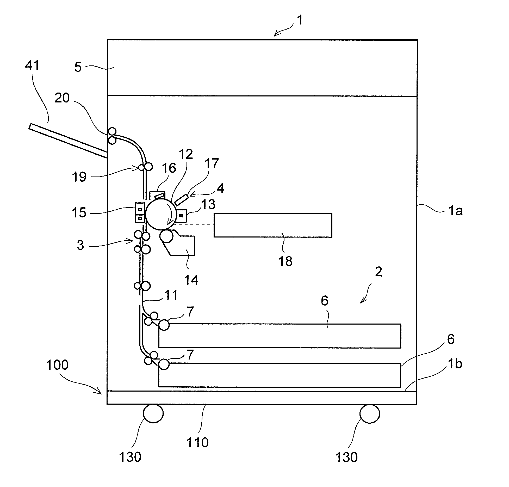
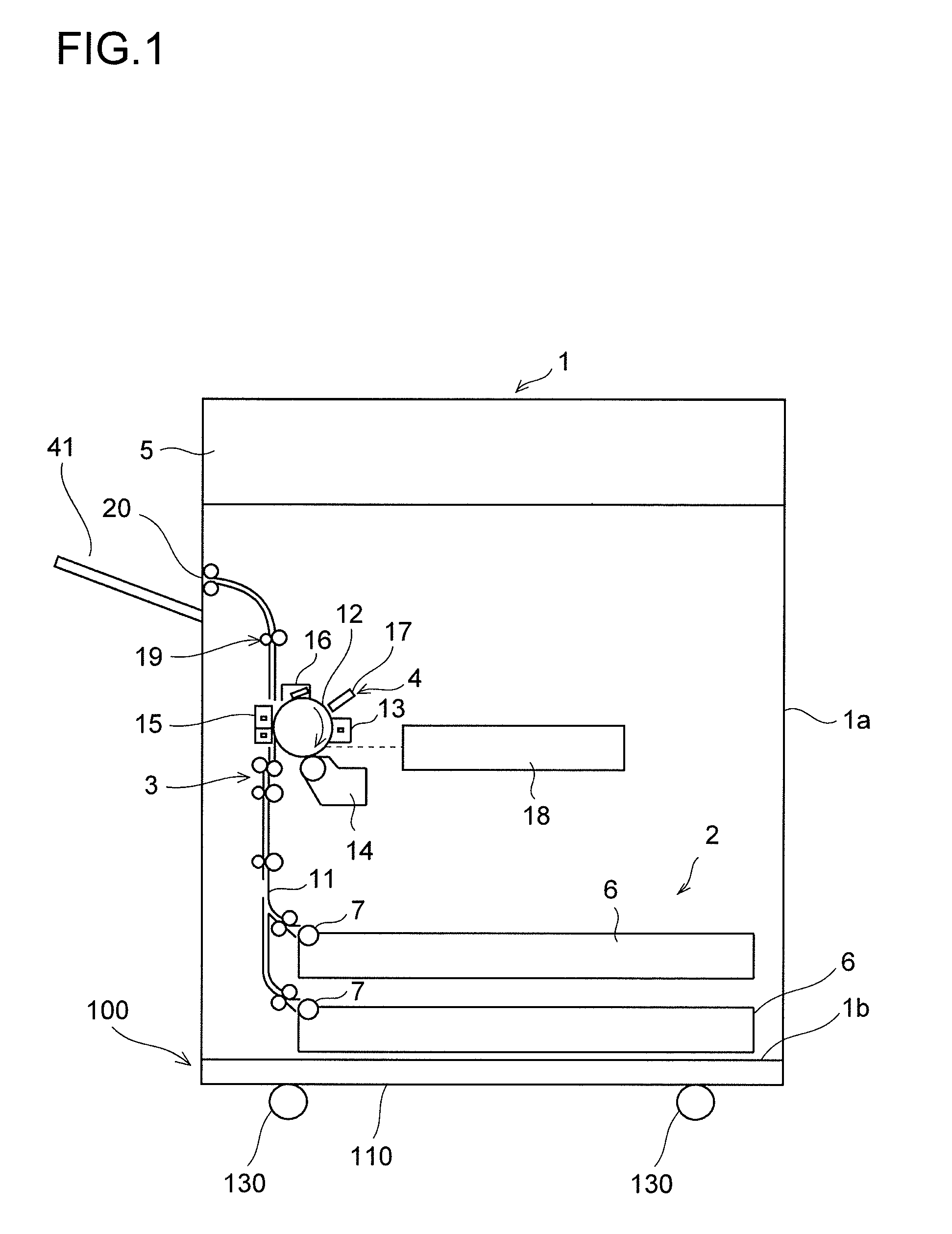
[0057]The leg-portion attachment structure 100 includes the support member 110, attachment plates 140, the casters 130, and fixing legs 121. The apparatus main body 1a of the image forming apparatus 1 is mounted onto an upper surface of the support member 110. The casters 130 and the fixing legs 121 are respectively arranged at four corners of the lower surface of the support member 110, the casters 130 being provided rotatably with respect to the support member 110, the fixing legs 121 being provided in a manner of holding the apparatus main body 1a with respect to a floor surface at the time of installation. Note that, in this embodiment, description is made on the premise that the floor surface side of the leg-portion attachment structure 100 is referred to as “lower surface” or “lower ...
second embodiment
[0088](Second Embodiment)
[0089]FIG. 6 is a perspective view of a main portion of an attachment plate according to a second embodiment of the present invention. Description is made of an attachment plate different from that in the first embodiment, and description of the same portions as those in the first embodiment is omitted in the following.
[0090]An attachment plate 240 includes a caster attachment portion 241, a first bent portion 242 formed by downward bending at a right angle of an outer edge in a side direction of the caster attachment portion 241 (direction of the arrows A-B of FIG. 3), and a first coupling portion 243 formed by outward bending at a right angle of a lower end portion of the first bent portion 242. The first coupling portion 243 is firmly attached to a pipe (support member) (not shown) with screws or by spot welding.
[0091]Further, the attachment plate 240 includes a second bent portion 244 formed by downward bending at a right angle of an inner edge in the si...
third embodiment
[0095](Third Embodiment)
[0096]FIG. 7 is a schematic partial sectional view taken along the side direction of an attachment plate according to a third embodiment of the present invention. The second bent portions are not provided in the third embodiment.
[0097]An attachment plate 340 includes the following provided on each end side thereof: a caster attachment portion 341, a first bent portion 342 formed by downward bending at a right angle of an outer edge in a side direction of the caster attachment portion 341 (direction of the arrows A-B of FIG. 3), and a first coupling portion 343 formed by outward bending at a right angle of a lower edge of the first bent portion 342. A connecting portion 345 is formed on an inner side of each of the caster attachment portions 341. The connecting portion 345 and the caster attachment portion 341 are formed on the same plane.
[0098]Each of the first coupling portions 343 is firmly attached to the lower surface of the pipe 111b with the screw 116 a...
PUM
 Abstract
Description
Claims
Application Information
 - R&D
- Intellectual Property
- Life Sciences
- Materials
- Tech Scout
- Unparalleled Data Quality
- Higher Quality Content
- 60% Fewer Hallucinations
Browse by: Latest US Patents, China's latest patents, Technical Efficacy Thesaurus, Application Domain, Technology Topic, Popular Technical Reports.
© 2025 PatSnap. All rights reserved.Legal|Privacy policy|Modern Slavery Act Transparency Statement|Sitemap|About US| Contact US: help@patsnap.com


