LED heat sink apparatus

a heat sink and heat sink technology, applied in the direction of lighting and heating apparatus, fixed installation, lighting support devices, etc., can solve the problems of complex, inefficient, costly, and/or damaged components contained inside the housing, and achieve the effect of easy assembly and low cos

Inactive Publication Date: 2014-10-14
RELUME TECH
View PDF49 Cites 31 Cited by
  • Summary
  • Abstract
  • Description
  • Claims
  • Application Information

AI Technical Summary

Problems solved by technology

However, such LED heat sink apparatuses suffer from certain disadvantages either because they rely on the housing being open to the surrounding atmosphere to cool the housing, which can leave components contained internal to the housing prone to damage due to exposure to external elements, or in the case of sealed assemblies, they rely on complex, inefficient, and / or costly means of cooling the housing.

Method used


Image

  • LED heat sink apparatus
  • LED heat sink apparatus
  • LED heat sink apparatus

Examples


Embodiment Construction

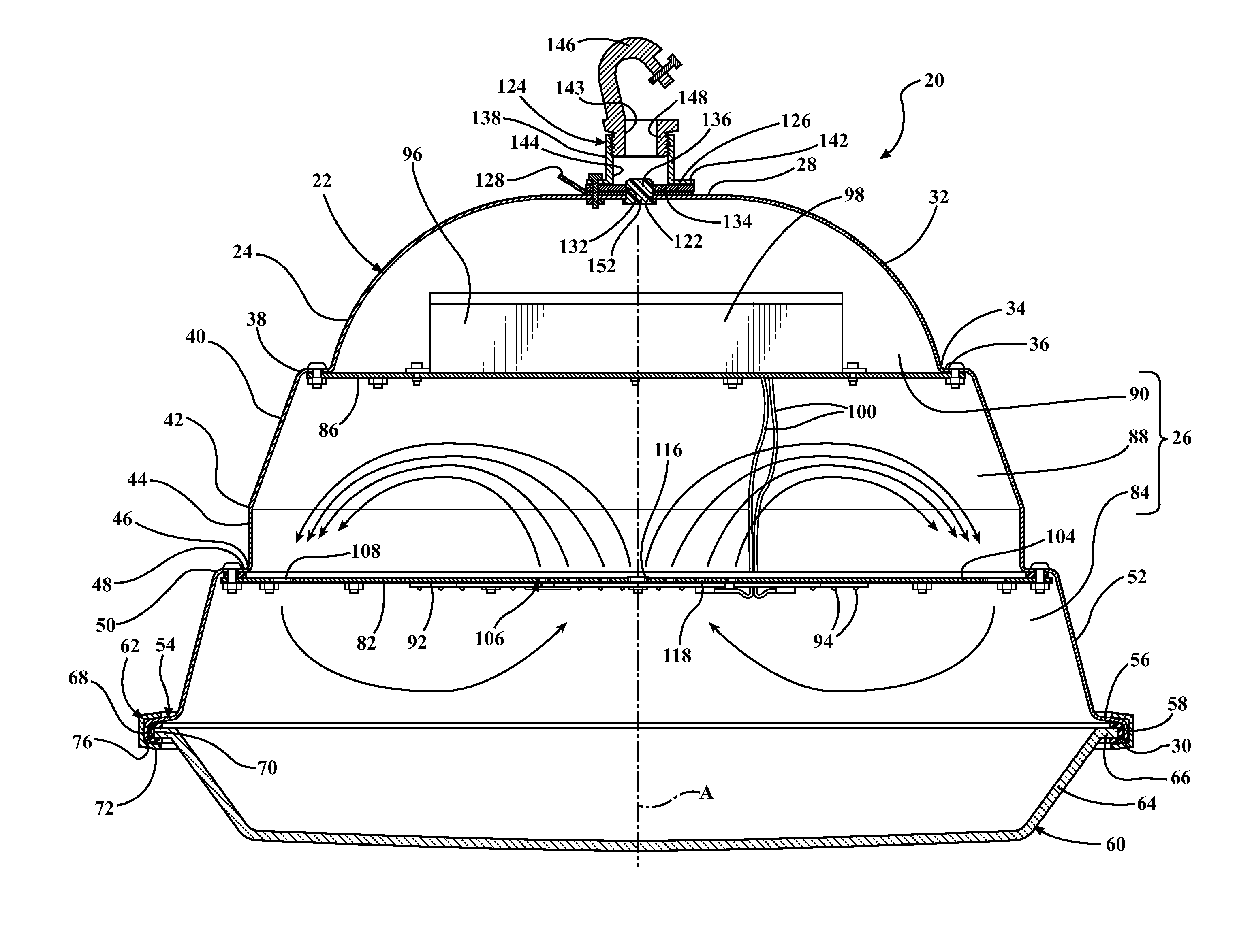
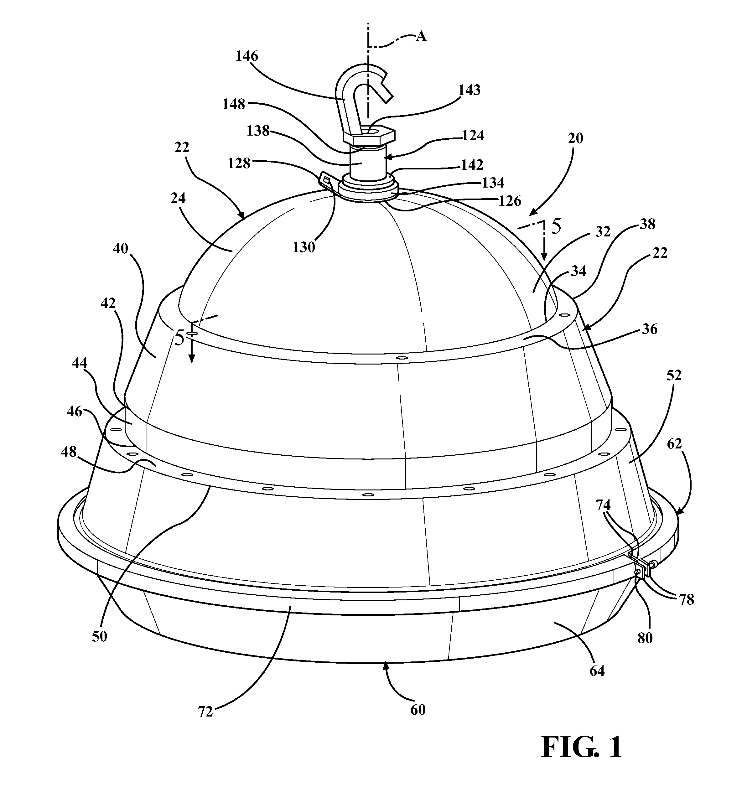
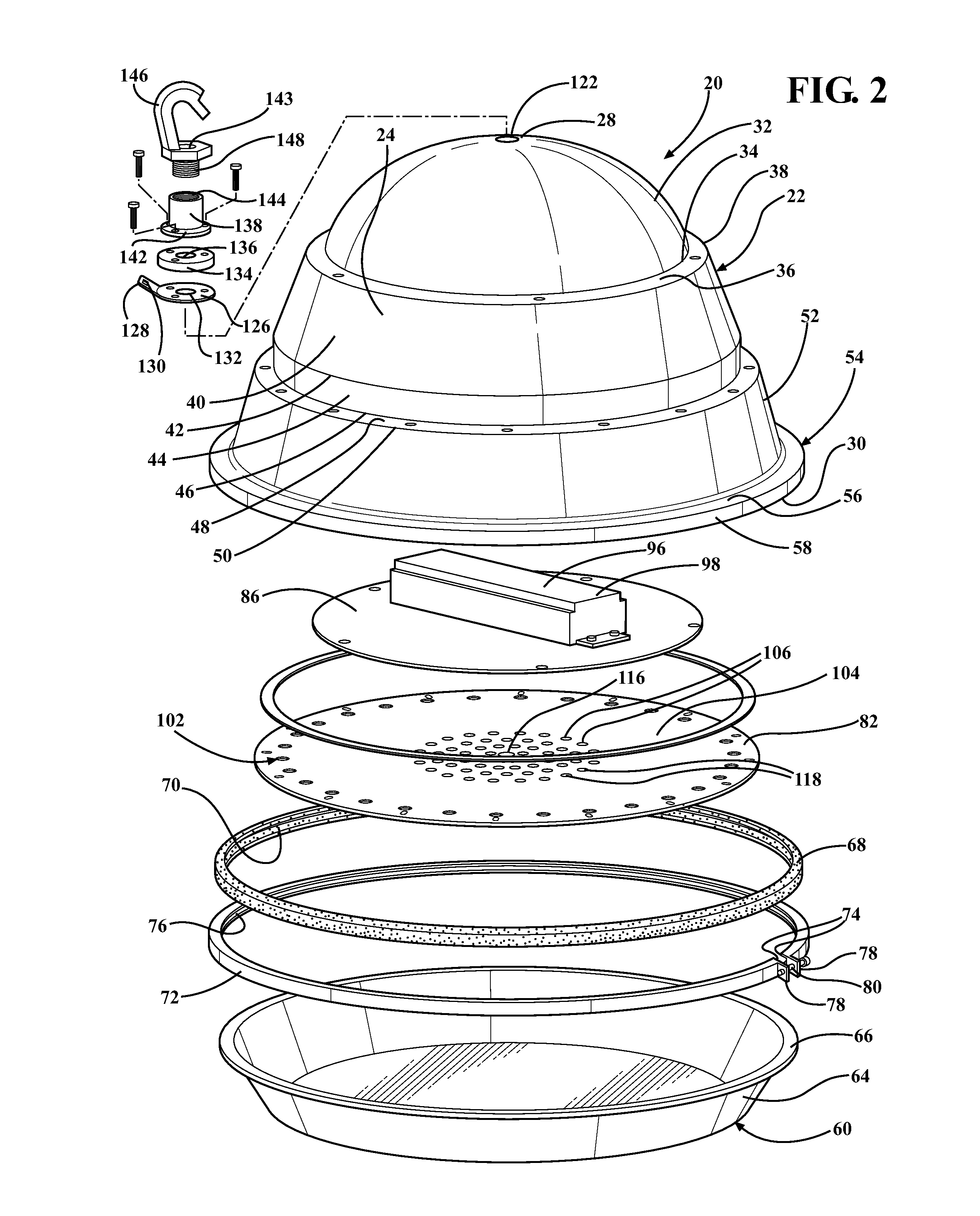
[0017]Referring to the Figures, wherein like numerals indicate corresponding parts throughout the several views, an LED heat sink apparatus 20 is generally shown for hanging from a mount.

[0018]The heat sink apparatus 20 includes a housing 22, generally indicated, that has a generally bell shape with a side wall 24 that extends about and along an axis A and presents an outer surface to define a chamber 26. The housing 22 extends between a closed end 28 that closes the chamber 26 and an open end 30 that opens the chamber 26. In the enabling embodiments, the housing 22 is made of a lightweight aluminum material, but is should be appreciated that other materials could be used, e.g. metal or plastic.

[0019]The side wall 24 of the housing 22 defines a top segment 32 that has a hemispherical shape and extends generally axially from the closed end 28 of the housing 22 to an edge 34 of the top segment 32. An upper step 36 extends annularly about and radially outwardly from the edge 34 of the ...


PUM


Abstract

An LED heat sink apparatus (20) comprising a housing (22) that defines a chamber (26). A downward platform (82) is connected with the housing (22) in the chamber (26) to define a bottom cavity (84) and a central cavity (88). LED's (94) are disposed in the bottom cavity (84) for emitting light through a lens (60). The downward platform (82) defines a plurality of holes (106, 108, 116, 118), and a solid ring (104) that has a substantially impervious surface to divide the holes (106, 108, 116, 118) into chimney holes (106, 116, 118) disposed radially inwardly from the solid ring (104) and the LED (94) for directing hot air heated by the LED (94) in the bottom cavity (84) of the chamber (26) into the central cavity (88), and return holes (108) disposed radially outwardly from the solid ring (104) and near the side wall (24) of said housing (22) for directing cool air in the central cavity (88) of the housing (22) that has been cooled by the side wall (24) of the housing (22) into the bottom cavity (84).

Description

CROSS-REFERENCE TO RELATED APPLICATION[0001]This application claims the benefit of application Ser. No. 61 / 734,013 filed Dec. 6, 2012.BACKGROUND OF THE INVENTION[0002]1. Field of the Invention[0003]An LED heat sink apparatus.[0004]2. Description of the Prior Art[0005]LED heat sink apparatuses are known in the art for containing LED's while preventing the LED's from overheating. One such LED heat sink apparatus is disclosed in U.S. Pat. No. 8,123,381 to Donald Lee Wray. The heat sink apparatus includes a housing that is disposed about an axis and defines a chamber. The housing includes a side wall that extends axially between a closed end that closes the chamber and an open end that opens the chamber. A lens is coupled with the closed end of the housing. A downward platform is connected with the side wall in the chamber to define a bottom cavity of the chamber between the downward platform and the lens, and a central cavity of the chamber between the downward platform and the closed ...

Claims


Application Information

Patent Timeline
Patent Type & Authority Patents(United States)
IPC IPC(8): F21L4/02F21S8/06F21V21/08F21V23/00F21V29/00F21V31/00F21Y101/02
CPCF21S8/06F21V29/2293F21V31/005F21V21/08F21V23/006F21Y2101/02F21V29/83F21Y2115/10
Inventor STRELCHUK, JOSEPH, D.
Owner RELUME TECH
Why Eureka
Try Eureka