Sensor system and method

a sensor and sensor technology, applied in the field of sensor systems, can solve the problems of large interference signals, high cost, and high cost, and achieve the effects of increasing the relative amplitude of the wanted signals, reducing the relative amplitude of the interference signals, and increasing the sensor sensitivity to the correct combination

Active Publication Date: 2014-10-14
THE UNIV OF SUSSEX
View PDF15 Cites 2 Cited by
  • Summary
  • Abstract
  • Description
  • Claims
  • Application Information

AI Technical Summary

Benefits of technology

[0012]Another aim of the invention, at least in its preferred form as described in this document, is to reduce the dynamic range requirement of a sensor by reducing the amplitude of large interference signals.
[0013]The present invention, at least in the preferred form as described, also seeks to render the operation of the sensor and the signal processing more precise by one or both of increasing the sensitivity to the correct combination of frequencies and reducing it at all others.
[0016]According to another aspect of the invention, there is provided a method of sensing and measuring electrical signals, comprising: detecting the electrical signals; applying the detected signals to an input of a sensor for generating a measurement signal as output; providing a feedback path from an output of the sensor to the input; situating a narrow band filter in the feedback path; controlling the frequency response of the filter whereby to tune the frequency response to a respective one of signals that are wanted signals and signals that represent interference signals; and arranging the sensor and the filter so as to alter the relative amplitudes of the wanted signals and the interference signals in order to increase the relative amplitude of the wanted signals and reduce the relative amplitude of the interference signals.
[0017]According to the invention, the sensor and the signal processing are tailored by increasing the sensor sensitivity to the correct combination of frequencies and reducing it at all others. One result of employing such a technique is to reduce the dynamic range requirement of the sensor.
[0018]Such reduction may be achieved by increasing the amplitude of the wanted signals and / or by reducing the amplitude of the interference signals. The frequency response of the sensor may thus be controlled according to the desired application. In addition, the selectivity of the sensor may be controlled if desired by adjusting or varying the Q factor of the filter. A very precise tuned response to the particular signalling environment may therefore be achieved, which has significant advantages.

Problems solved by technology

Various problems associated with the use of extremely sensitive sensors are well known.
One principal problem encountered is that of dynamic range.
This introduces a conflict with the need for high gain in order to amplify small signals and lift them above the noise floor of subsequent stages, such as in analogue to digital (A / D) converters, since such gain cannot be so large that it leads to saturation from large interference signals.
This, however, produces a system which is sensitive to field gradients instead of fields, thus rendering it unsuitable for applications where the source is remote from the sensor.
A problem with the latter approach, however, is that digitising the signal may produce a large dynamic range between the wanted signal and the interference signal.
This A / D converter is seven times more expensive than a typical 16 bit A / D converter which will display >90 dB of dynamic range and >100 kHz of bandwidth.
Clearly, the 24 bit converter is not only a very expensive option, but it also fails to meet the above requirement for a 150 dB dynamic range.
Although the problems relating to the use of extremely sensitive sensors are described above in relation to magnetometers, nevertheless the competing requirements of low noise and high dynamic range are common to many sensor systems, including electrical potential sensors as well.
It is worth noting that in almost all real world applications of sensors, the sensor sensitivity is limited not by the inherent capability of the sensor or the instrumental noise but by the ability of the system to encompass the full dynamic range of environmental noise and interference.

Method used


Image

  • Sensor system and method
  • Sensor system and method
  • Sensor system and method

Examples


Embodiment Construction

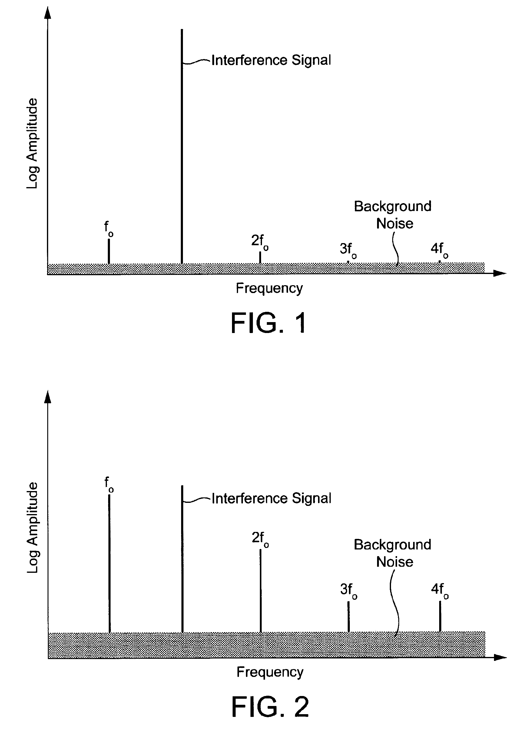
[0037]The invention will now be described with reference to the drawings. Reference is made firstly to FIGS. 1 and 2 for an explanation of the principles of the invention. These Figures are comparative signal diagrams showing frequency against a logarithmic value for amplitude for the various signals encountered by a sensor in practice, including wanted or detection signals and unwanted or interference signals.

[0038]FIG. 1 shows a typical situation where a large interference signal is present amongst the signals received by a conventional sensor. In order to prevent saturation or clipping of the sensor, which would result in dead sensing regions and loss of the wanted signals (fo, 2fo, 3fo and 4fo), the gain of the sensor has hitherto been restricted to a value which keeps the interference signal within the dynamic range of the system, and this introduces the problems referred to above.

[0039]By comparison, in the example of FIG. 2, the frequency response of the sensor has been tailo...


PUM


Abstract

The present invention provides a sensor system and a corresponding sensing method employing the sensor system. The sensor system comprises a sensor (12) having an input (20) and an output (22), a feedback path (16) from the output to the input, and a filter (14; 92) in the feedback path. The filter comprises a narrow band filter, which is tuned or tunable to a respective one of signals that are wanted signals and signals that represent interference signals. The sensor and the filter are arranged so as to alter the relative amplitudes of the wanted signals and the interference signals in order to increase the relative amplitude of the wanted signals and reduce the relative amplitude of the interference signals.

Description

FIELD OF THE INVENTION[0001]The present invention concerns a sensor system for use for the sensitive measurement and detection of signals in a wide variety of applications, and a corresponding sensing method.BACKGROUND OF THE INVENTION[0002]Various problems associated with the use of extremely sensitive sensors are well known. One principal problem encountered is that of dynamic range. A very high sensitivity detector will, of necessity, be required both to accommodate extremely small detected signals and at the same time avoid saturation in the presence of large amplitude interference signals. This introduces a conflict with the need for high gain in order to amplify small signals and lift them above the noise floor of subsequent stages, such as in analogue to digital (A / D) converters, since such gain cannot be so large that it leads to saturation from large interference signals.[0003]The principal interference signals are usually caused by mains related frequencies. These are norm...

Claims


Application Information

Patent Timeline
Patent Type & Authority Patents(United States)
IPC IPC(8): G01R23/02H03H11/12
CPCH03H11/1217H03H11/1291
Inventor PRANCE, ROBERTPRANCE, HELENHARLAND, CHRISTOPHER
Owner THE UNIV OF SUSSEX
Why Eureka
Try Eureka