Apparatus and method for monitoring extra long distance optical cables by using one monitoring wavelength

An ultra-long, distance technology, applied in the field of ultra-long-distance optical cable monitoring

Inactive Publication Date: 2015-12-23
GUILIN G LINK TECH
View PDF6 Cites 2 Cited by
  • Summary
  • Abstract
  • Description
  • Claims
  • Application Information

AI Technical Summary

Problems solved by technology

In this way, when using the double-ended monitoring method for online monitoring of optical cables longer than 150km, it is not possible to simply add optical signal filters at both ends to isolate the mutual interference of the monitoring signals at both ends

Method used


Image

  • Apparatus and method for monitoring extra long distance optical cables by using one monitoring wavelength
  • Apparatus and method for monitoring extra long distance optical cables by using one monitoring wavelength
  • Apparatus and method for monitoring extra long distance optical cables by using one monitoring wavelength

Examples


Embodiment

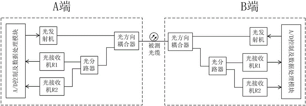
[0035] see figure 1 , this embodiment is composed of two monitoring terminals A and B, the two monitoring terminals A and B have the same principle structure, but different circuit parameters.

[0036] A device that uses one monitoring wavelength to realize ultra-long-distance optical cable monitoring, including two monitoring terminals with the same structure, namely A monitoring terminal and B monitoring terminal,

[0037] The monitoring terminal includes an A / D control and data processing module, an optical transmitter, an optical directional coupler, an optical receiver R1, an optical receiver R2, and an optical splitter;

[0038] The A / D control and data processing module is connected to the optical transmitter, optical receiver R1, and optical receiver R2. One end of the optical splitter is connected to the optical receiver R1 and optical receiver R2, and the other end is connected to the optical directional coupler. The transmitter is connected with the optical directi...


PUM


Abstract

The invention discloses an apparatus and a method for monitoring extra long distance optical cables by using one monitoring wavelength. The method comprises the following steps: 1) checking the output state of an optical receiver R2; 2) if the output state of the optical receiver R2 is that "a test channel is busy", entering the 1) step again; 3) if the output state of the optical receiver R2 is that "the test channel is idle", transmitting a test channel occupation signal; 4) if the output state of the optical receiver R2 is that "the test channel is busy", entering the 1) step again; 5) if the output state of the optical receiver R2 is always that "the test channel is idle", entering an OTDR test state; 6) entering a test termination silence period; and 7) after the test is terminated, receiving an OTDR test command again. The method has the advantages that a time division multiplexing mode is used on both ends to use one monitoring wavelength to monitor the extra long distance optical cables.

Description

technical field [0001] The invention relates to the field of optical fiber communication, in particular to a device and method for realizing ultra-long-distance optical cable monitoring by using one monitoring wavelength. Background technique [0002] With the development of optical communication, the scale of optical cable network has expanded rapidly, and the online monitoring system of optical cable plays an important role in the work of maintaining the optical cable network efficiently and quickly. The optical cable monitoring system uses OTDR technology to detect the fault of the monitored optical cable by monitoring the attenuation characteristic change of the optical fiber core in the optical cable, and perform fault location. [0003] In theory, only one monitoring wavelength needs to be used to monitor a fiber. For example, in the offline monitoring mode, you only need to select a wavelength among 1310nm, 1550nm, 1625nm, and 1650nm as the monitoring wavelength. Ho...

Claims


Application Information

Patent Timeline
Patent Type & Authority Applications(China)
IPC IPC(8): H04B10/071
Inventor 彭怀敏李立汉王强肖丹谊
Owner GUILIN G LINK TECH
Why Eureka
Try Eureka