Fixed rate EGR system

A LP-EGR, HP-EGR technology, applied in charging system, electrical control, machine/engine, etc., can solve problems such as long conveying delay, improve durability, improve EGR mixing, reduce system cost and complexity Effect

Inactive Publication Date: 2014-04-16
FORD GLOBAL TECH LLC
View PDF6 Cites 2 Cited by
  • Summary
  • Abstract
  • Description
  • Claims
  • Application Information

AI Technical Summary

Problems solved by technology

The LP-EGR loop has a long delivery delay due to the exhaust gas having to pass through the turbo compressor, high pressure air intake duct, charge air cooler and intake manifold before reaching the combustion chamber

Method used


Image

  • Fixed rate EGR system
  • Fixed rate EGR system
  • Fixed rate EGR system

Examples


Embodiment Construction

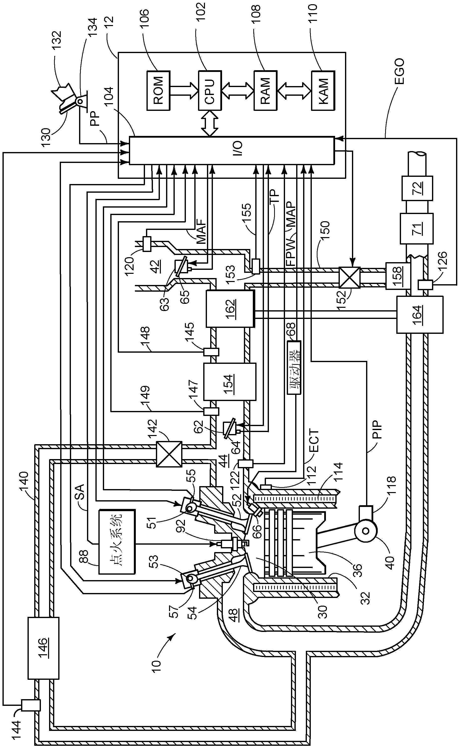
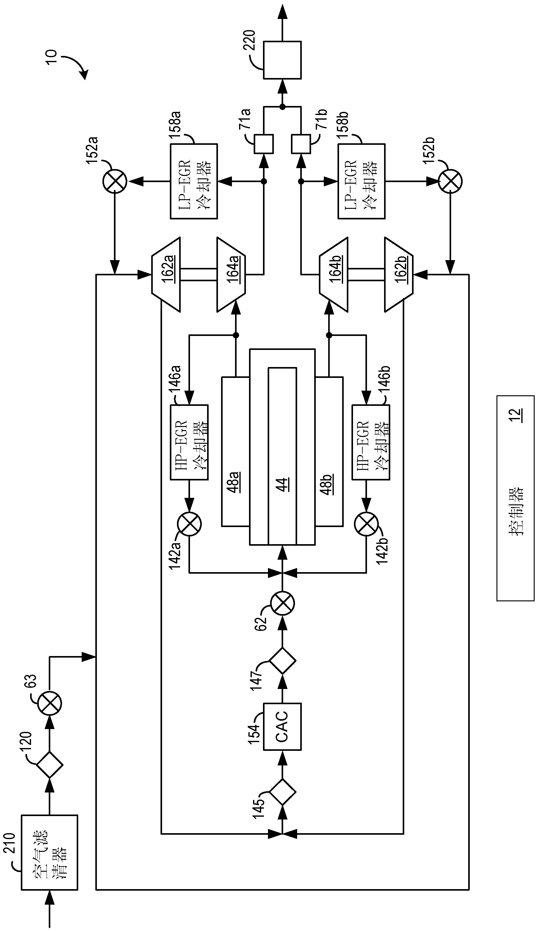
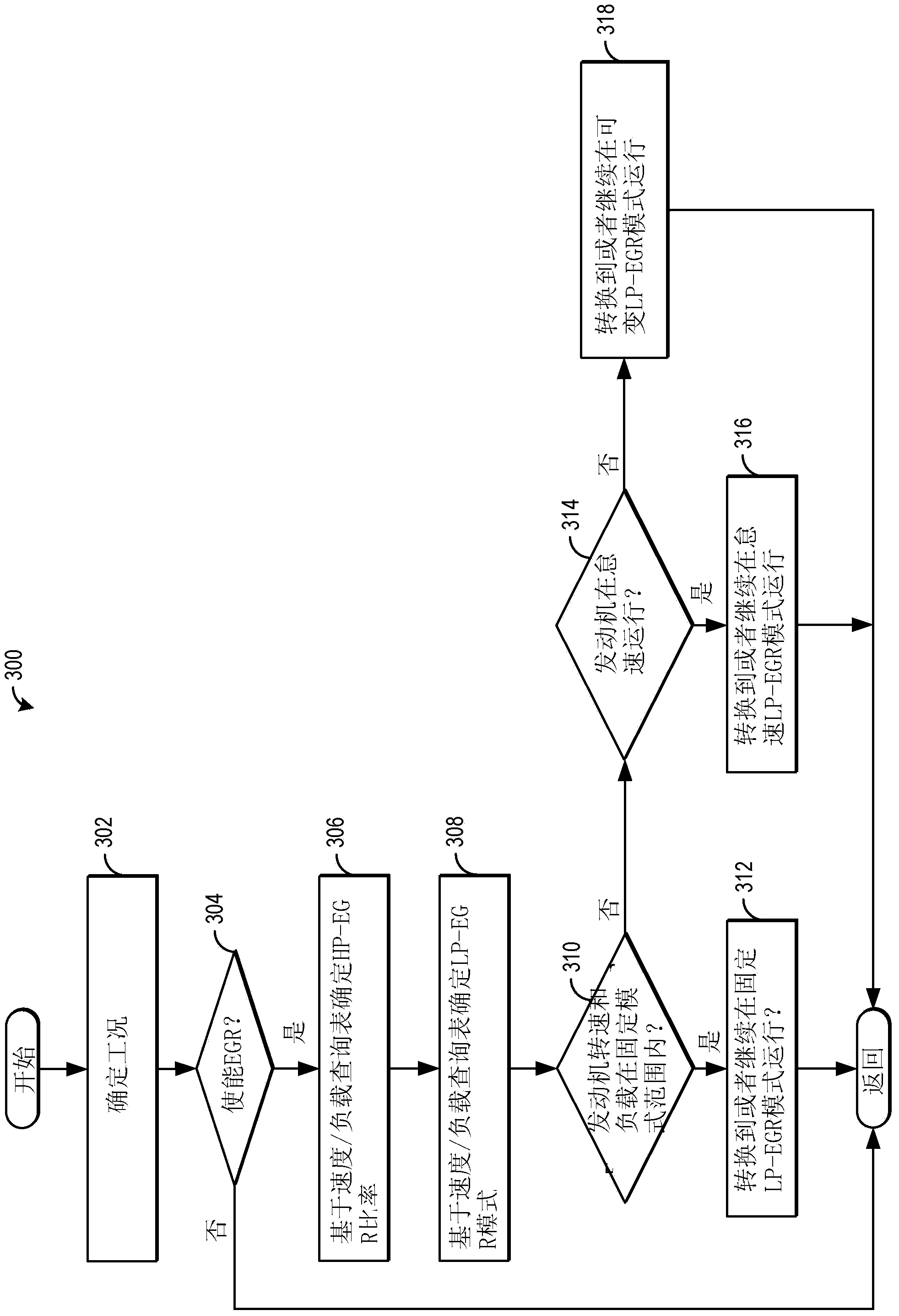
[0016] This specification relates to an EGR system coupled to a turbocharged engine in a motor vehicle. In a non-limiting example, an engine can be configured as figure 1 A portion of the system described wherein the engine includes at least one cylinder, a control system, a turbocharger and an exhaust gas recirculation system, among other features. The engine can be configured with figure 2 Multiple cylinder banks as described in . figure 1 and figure 2 The system can be used for example Figure 3-6 The example method operation described in . Various EGR operating modes can be mapped by engine speed-load (such as in Figure 7 the one depicted in) OK. Figure 8A and Figure 8B description in Figure 3-Figure 6 Various engine operating parameters during execution of the method.

[0017] now refer to figure 1 , which shows a schematic diagram of one cylinder of a multi-cylinder engine 10 that may be included in the propulsion system of the illustrated automobile. En...


PUM


Abstract

A method is provided for controlling EGR flow in a turbocharged engine. The method comprises operating a low-pressure exhaust gas recirculation (LP-EGR) system at a fixed EGR percentage rate of fresh airflow from mid-load down to a minimum engine load, even as load changes. In this way, errors in the delivered LP-EGR rate during transient conditions may be alleviated by providing a fixed EGR percentage of fresh airflow at all engine loads within a fixed mode range.

Description

technical field [0001] The present application relates to the control of exhaust gas recirculation systems in motor vehicles. Background technique [0002] Exhaust gas recirculation (EGR) systems separate a portion of exhaust gas back into the intake air to cool combustion temperatures and reduce throttling losses, thus improving vehicle emissions and fuel economy. In turbocharged engines, the EGR system may include a low-pressure EGR (LP-EGR) circuit, a high-pressure EGR (HP-EGR) circuit, or both. The LP-EGR circuit separates the exhaust gas after it passes through the turbocharger's turbine and injects the gas before the compressor, while the HP-EGR separates the exhaust gas before the turbine and injects the gas after the intake throttle. Conventionally, the amount of LP-EGR and / or HP-EGR through the EGR system is measured and adjusted based on engine speed and load during engine operation to maintain desired combustion stability of the engine while providing emissions a...

Claims


Application Information

Patent Timeline
Patent Type & Authority Applications(China)
IPC IPC(8): F02M25/07F02D41/00
CPCF02D2041/0017F02M25/0707F02B29/0406F02M25/0709F02M25/0731F02M25/0711F02D41/005F02M25/0748F02B37/007F02D41/0065F02D9/02Y02T10/47F02D41/0077F02M25/0744F02M25/0732F02M26/05F02M26/06F02M26/08F02M26/28F02M26/24F02M26/38F02M26/42Y02T10/40F02D41/0005
Inventor D·J·斯泰爱兹J·希尔迪奇W·C·罗那
Owner FORD GLOBAL TECH LLC
Why Eureka
Try Eureka