Apparatus for multi-spectral imaging of point event detection

a multi-spectral imaging and event technology, applied in the direction of optical radiation measurement, instruments, spectrometry/spectrophotometry/monochromators, etc., can solve the problems of increasing processing capacity, unable to detect the rapid change of spectral features in any band, and unable to retrofit one of these optical front-end devices onto existing munitions and imagers,

Inactive Publication Date: 2014-10-14
THE UNITED STATES OF AMERICA AS REPRESETNED BY THE SEC OF THE AIR FORCE
View PDF35 Cites 10 Cited by
  • Summary
  • Abstract
  • Description
  • Claims
  • Application Information

AI Technical Summary

Problems solved by technology

In addition to generating large quantities of data for analysis, these devices can miss rapidly changing spectral features in any band (or bands) since only one color is collected per frame.
In addition to the fact that the large amount of spectral data requires greater processing capacity for analysis, the optical front-ends of many of these spectrometers include complex optics that have optics with mechanical parts and / or may require precision alignment.
To retrofit one of these optical front-end devices onto existing munitions and imagers is extremely difficult, cost prohibitive, and in some cases impossible due to the size and weight constraints.
Processing all of these bands is challenging and requires greater hardware capacity and time to process the data.
It also is more prone to errors due to the output response of various sources that may be present in the field of view and that may amplify or attenuate the signal of the event being detected.
This situation results in false alarms or missed targets due to the above mentioned artifacts.
However, in addition to the cost and complexity factors of designing such devices, the data processing requirements will add time and expense to the data analysis hardware of the existing munitions and imagers.

Method used


Image

  • Apparatus for multi-spectral imaging of point event detection
  • Apparatus for multi-spectral imaging of point event detection
  • Apparatus for multi-spectral imaging of point event detection

Examples


Embodiment Construction

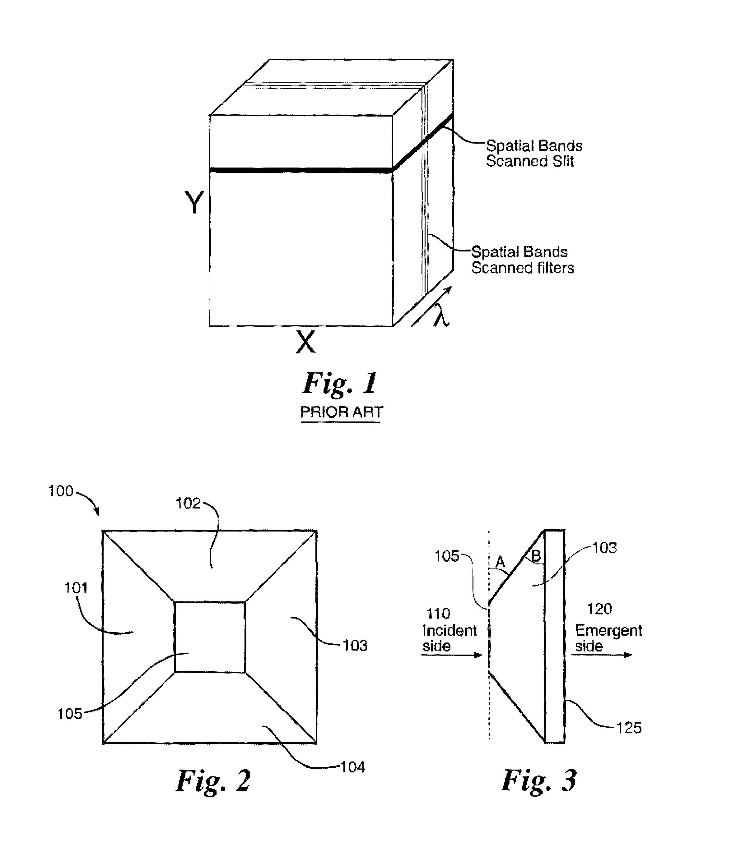
[0021]As shown in FIGS. 2 and 3, a multi-spectral prism-lens 100 includes an incident side 110 and an emergent side 120. The incident side 110 comprises four side sections 101, 102, 103, 104 and a center section 105. The emergent side 120 has a planar surface 125. The surfaces of the side sections 101, 102, 103, 104, and the center section 105 are planar. The surface of each side section 101, 102, 103, 104 is disposed at an angle of incline “A” with respect to the surface of the center section 105. The angle of incline “A” may be the same or different for each side section 101, 102, 103, 104. If the surface of the center section 105 is parallel to the surface 125 of the emergent side 120, as shown in FIGS. 2 and 3, the angle of incline “A” of each side section 101, 102, 103, 104 equals the angle of decline “B” of each side section 101, 102, 103, 104 with respect to the surface 125 of the emergent side 120. If the surface of the center section 105 is parallel to the surface 125 of th...


PUM

PropertyMeasurementUnit
wavelengthaaaaaaaaaa
energyaaaaaaaaaa

Abstract

A multi-spectral system characterizes point events and other rapidly-occurring events by filtering spectral bands from a point event to form spectral diagrams of the event.

Description

RIGHTS OF THE GOVERNMENT[0001]The invention described herein may be manufactured and used by or for the Government of the United States for all governmental purposes without the payment of any royalty.BACKGROUND[0002]In the field of imaging, spectral imaging provides a way to qualify the spatial and spectral characteristics of a scene within a field of view. Spectral imaging may be used to detect such as point threats that are dynamic in nature, and which occur and evolve rapidly in time with respect to their environment. An example of this kind of detection could be the observation of an explosion from a great distance as from an airborne platform or space. Various devices are used to provide spectral imaging of an event from a scene on a single detector or an array of detectors. Imaging spectrometers can be scanning devices or spatially multiplexing imagers that scan a slit over the entire field of view of the sensor to acquire the complete image. In this case, the sensor is a mod...

Claims


Application Information

Patent Timeline
Patent Type & Authority Patents(United States)
IPC IPC(8): G01N21/25
CPCG01J3/2823G01N21/25G01J3/0205G01J3/0208G01J3/0229G01J3/027G01J3/14
Inventor EWING, WILLIAM S.VAKIL, MOHAMMAD I.
Owner THE UNITED STATES OF AMERICA AS REPRESETNED BY THE SEC OF THE AIR FORCE
Why Eureka
Try Eureka