Dual input interferometer beamsplitter tilt control system and flexure mounting

a technology of tilt control system and interferometer, which is applied in the field of optical scientific instruments, can solve the problems of less stable interferometer itself, achieve the effects of preserving optical flatness, preserving optical flatness of relatively soft materials, and minimizing external stresses

Active Publication Date: 2014-10-14
THERMO ELECTRONICS SCI INSTR LLC
View PDF12 Cites 1 Cited by
  • Summary
  • Abstract
  • Description
  • Claims
  • Application Information

AI Technical Summary

Benefits of technology

[0013]Another aspect of the present invention provides for a flexure mounted moving beamsplitter assembly that includes a beamsplitter substrate; a resilient membrane configured coupled about the periphery of the beamsplitter substrate and further coupled to a support structure; wherein the resilient membrane minimizes induced external stresses directed through the support structure and thus aids in preserving optical flatness; a plurality of magnetic means coupled to a predetermined surface of the beamsplitter substrate; and a plurality of coils configured to couple matched and / or mismatched predetermined magnetic forces with the plurality of magnetic means, wherein the matched and / or mismatched predetermined magnetic forces enables linear and / or tilting movements of the beamsplitter substrate.
[0014]Accordingly, the present invention, as described herein, provides for a novel soft beamsplitter mounting system that protects the beamsplitter substrate, as configured in an interferometer, from external stresses so as to the preserve optical flatness of the relatively soft material. However, although such a soft beamsplitter mounting configuration protects the beamsplitter substrate, the interferometer itself is less stable because the mounts of the present invention allows the beamsplitter to tilt more easily than other components held in the interferometer. Thus, the present invention combines an improved dual tilt control system to overcome the instabilities resultant from the inexpensive soft mounting system to provide for an overall rugged instrument.

Problems solved by technology

However, although such a soft beamsplitter mounting configuration protects the beamsplitter substrate, the interferometer itself is less stable because the mounts of the present invention allows the beamsplitter to tilt more easily than other components held in the interferometer.

Method used


Image

  • Dual input interferometer beamsplitter tilt control system and flexure mounting
  • Dual input interferometer beamsplitter tilt control system and flexure mounting
  • Dual input interferometer beamsplitter tilt control system and flexure mounting

Examples


example method

of System Operation

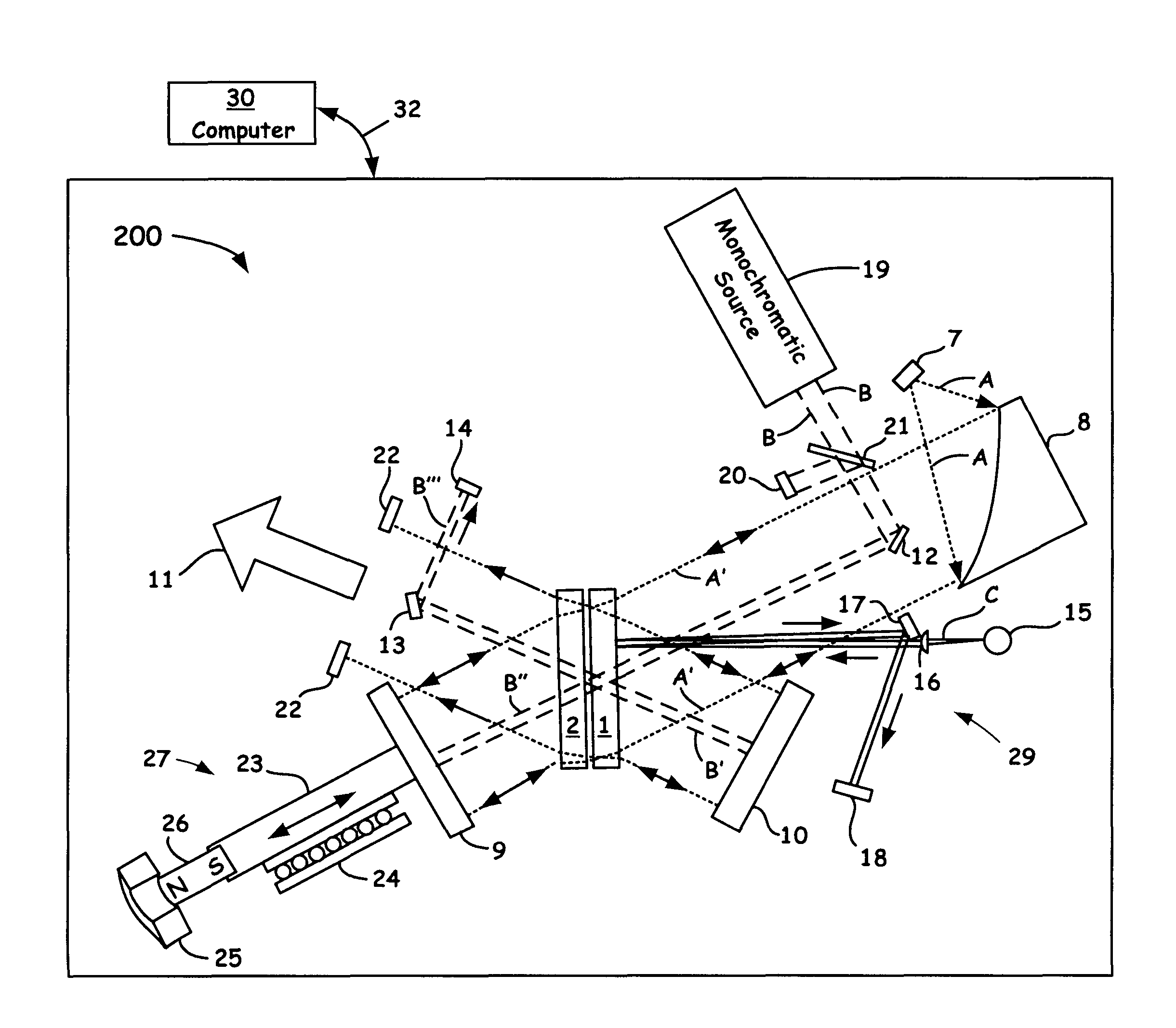
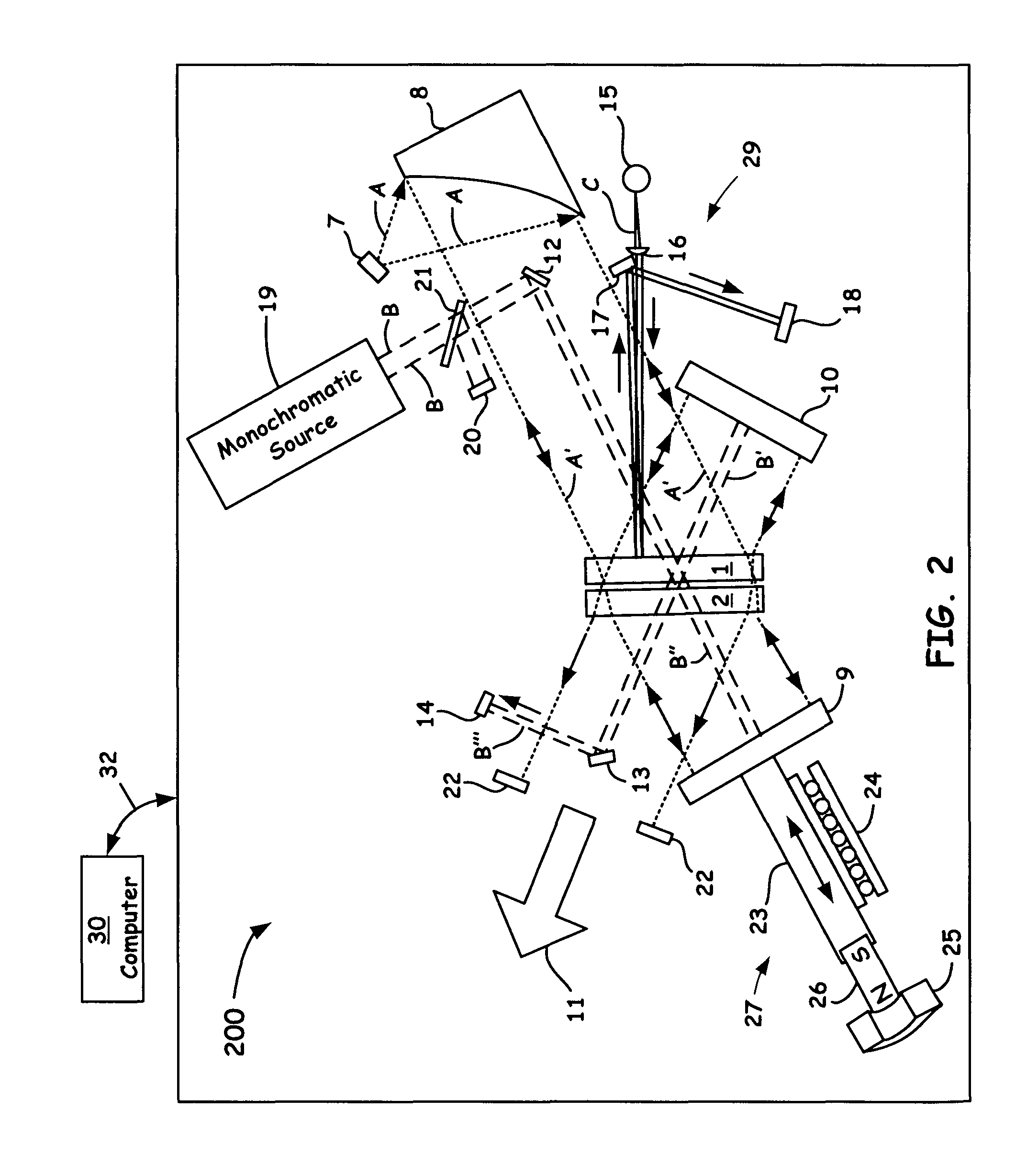
[0085]On power up, an optical phase velocity and tilt control system as disposed within the overall system 200 of FIG. 2 is inoperative and thus produces no output signal. However, the wide range tilt correction system 29 of FIG. 2 as coupled to, for example, similar circuitry as shown in FIG. 3B, provides a signal as soon as the source 15 of system 29 starts operating. In less than about 1 second, a tilt error that can be greater than about 10,000 arc seconds can be reduced to less than about 5 arc seconds so that there is a strong optical signal provided for the velocity servo circuit before it can attempt to operate.

[0086]After such optical signals are sufficiently full sized, the velocity servo circuit portion (e.g., as shown in FIG. 3A) can start and can (but does not have to) turn on the optical phase tilt control system (as shown in box 50 of FIG. 3A), as discussed above. The output signals 52, 54 of the circuit shown in FIG. 3A can thus be added to the err...


PUM


Abstract

A novel soft beamsplitter mounting system as part of an interferometer to protect the beamsplitter substrate from external stresses and thus preserve optical flatness is introduced. The soft mounting system enables such protection by being more flexible that the beamsplitter substrate so external forces deforms the mount rather than the beamsplitter. Although the soft beamsplitter mounting configurations disclosed herein protects the beamsplitter, the interferometer itself is less stable because the mounts of the present invention allows the beamsplitter to tilt more easily than other components held in the interferometer. The improved tilt control embodiments of the present invention turns this seemingly deleterious effect into a cost saving benefit by using the inexpensive soft mounting system as a flexure to allow an improved active control system to maintain tilt alignment in a system that is more rugged than conventional interferometers.

Description

BACKGROUND OF THE INVENTION[0001]1. Field of the Invention[0002]The present invention relates to the field of optical scientific instrumentation. More specifically, the present invention relates to a dual tilt control system that includes a soft flexure beamsplitter assembly as incorporated in a Fourier-Transform infrared (FTIR) scanning interferometer.[0003]2. Discussion of the Related Art[0004]An optical interferometer used in a scientific analytical instrument relies on the interference of superimposed optical beams as part of the interrogation means. When configured as a Michelson Fourier-Transformed infrared (FTIR) instrument, the optical output of the interferometer is called an interferogram. The FTIR interferometer itself often includes a beamsplitter and two mirrors, one that is conventionally stationary, and one which is conventionally mobile. The mobile mirror moves along the optic axis while staying optically perpendicular to the light beam at all times. The movement of ...

Claims


Application Information

Patent Timeline
Patent Type & Authority Patents(United States)
IPC IPC(8): G01B11/02G01B9/02G01J3/453G02B27/10
CPCG01J3/453G02B27/1013G02B27/10G01B9/02068
Inventor COFFIN, JOHN, MAGIE
Owner THERMO ELECTRONICS SCI INSTR LLC
Why Eureka
Try Eureka