Force-resistant panel

a technology of force-resistant panels and panels, applied in the direction of warlike protection, protective equipment, safes, etc., can solve the problems of inadequate setback, insufficient setback alone, and building might be expected to withstand, so as to reduce building stress and limit damage inside the building

Active Publication Date: 2014-10-21
THERM O LITE
View PDF4 Cites 20 Cited by
  • Summary
  • Abstract
  • Description
  • Claims
  • Application Information

AI Technical Summary

Benefits of technology

[0006]The present disclosure describes a blast panel which is suitable for being retrofit into an existing window sill and spaced interiorly from an existing window pane. The blast panel described herein is movable, such that during an explosion, the panel will move toward the interior of the building, translating the explosive force of the blast into kinetic movement of the panel, thereby reducing the stresses on the building, and limiting damage inside the building.

Problems solved by technology

However, the stresses a building might be expected to withstand in its lifetime are no longer limited to natural phenomena, but now include the possibility of acts of terror.
Unfortunately, in some cases adequate setback is not possible.
As such, in some cases setback alone is insufficient to protect a building.
The most vulnerable part of a building during a blast is typically the windows, as the glass on windows will shatter during an explosion, the sharp pieces becoming high-speed projectiles in the building.
It is costly to retrofit an existing building with explosion-resistant glass, and typically involves expensive reinforcement and reengineering of the window sills.
Such a retrofit typically requires use of the building be suspended or altered during construction.
Such designs are insufficient due to the cost and complexity of building the parabolic stop and the stresses related to the bending of the window.
Such designs are also insufficient due to the stresses on the building at the sills where the panels are anchored.
Further, deformation of the panels during a blast can be non-uniform, causing the panel to improperly engage the stop and come free during a blast.

Method used


Image

  • Force-resistant panel
  • Force-resistant panel
  • Force-resistant panel

Examples


Embodiment Construction

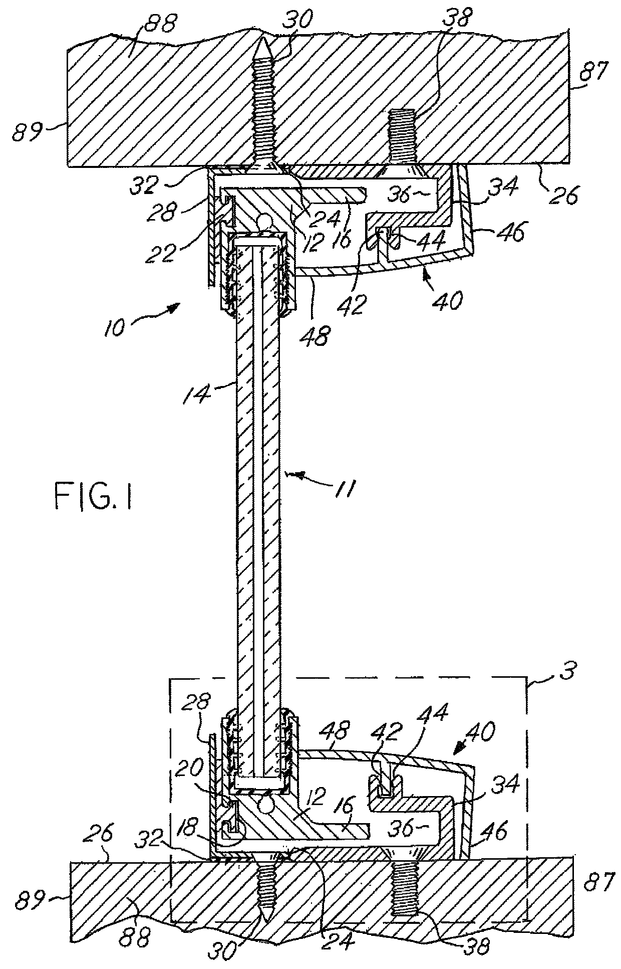
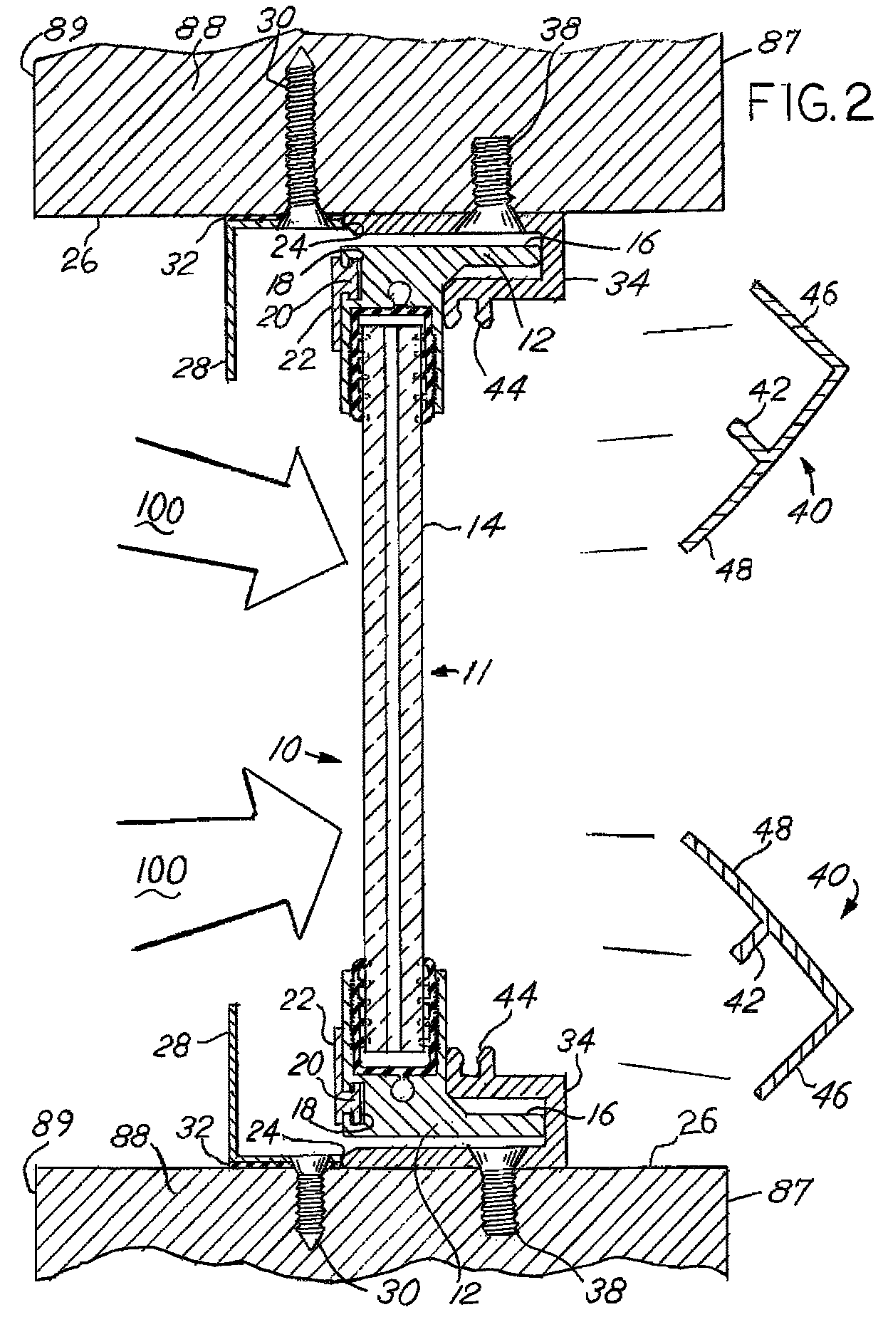
[0015]The present disclosure describes a force-resistant panel system 10 as shown in FIG. 1 which is designed to mitigate the effects of a blast 100 or explosion to the windows of a building. As used herein, “exterior” generally refers directionally to the side of the force-resistant panel system 10 which faces the outside of the building, and “interior” generally refers directionally to the side of the force-resistant panel system 10 which faces the inside of the building. While the typical installation involves an exterior window to a building, it can be installed in any wall where it is possible an explosion can come from one side. The building wall 88 has an interior surface 87 and an exterior surface 89, with a window opening. The window opening is bordered by a sill 26, which is a surface that connects the interior surface 87 and the exterior surface 89. The sill 26 can be part of the window panel system that is installed as a unit into a wall 88.

[0016]The system 10 shown in F...


PUM


Abstract

A force resistant panel system is provided where a window pane is bordered by a sash and magnetically attracted to an exterior flange. The exterior flange is attached to an opening in a wall, facing outward. An interior flange with a channel is attached to the inside and facing inward. The exterior flange and interior flange combine to form a channel for which the window pane can travel in the event of a blast. Decorative trim snaps into a groove on the interior flange and generates static outward pressure against the sash.

Description

CROSS REFERENCE TO RELATED APPLICATIONS[0001]This application claims the benefit of U.S. Provisional Application No. 61 / 825,574, filed May 21, 2013, the disclosures of which are hereby incorporated by reference.BACKGROUND OF THE INVENTION[0002]Buildings have traditionally been engineered to withstand the environmental forces expected in the region in which they reside. For example, a building in California might be designed to withstand earthquakes while a building in Florida might be designed to withstand hurricanes. However, the stresses a building might be expected to withstand in its lifetime are no longer limited to natural phenomena, but now include the possibility of acts of terror. As such, protection against the forces associated with explosions is necessary for some buildings which might be the targets of such acts of terror.[0003]One common defense against explosions has been to prevent access to the target building. One way to prevent access to a building is to increase ...

Claims


Application Information

Patent Timeline
Patent Type & Authority Patents(United States)
IPC IPC(8): E05G1/024E05G1/026F41H5/26E06B5/10E06B5/12
CPCE05G1/026E05G1/024E06B5/10F41H5/26E06B5/12E06B3/5842E06B3/5481F41H5/013E06B3/585
Inventor CHAMPLIN, RICHARD
Owner THERM O LITE
Why Eureka
Try Eureka