Method for relaying data in multi-hop cellular system

a multi-hop cellular system and relaying technology, applied in the direction of transmission monitoring, repeater circuits, line-transmission details, etc., can solve the problems of blind routing, inability to employ a centralized architecture using the current wireless network architecture, and suffer from a huge load upon the calculation of fedback channel information, so as to reduce the complexity of signaling and calculation, reduce the probability of decoding uplink signals, and prevent the effect of lowering gains

Active Publication Date: 2014-10-21
IND ACADEMIC COOP FOUND YONSEI UNIV
View PDF6 Cites 5 Cited by
  • Summary
  • Abstract
  • Description
  • Claims
  • Application Information

AI Technical Summary

Benefits of technology

[0030]The random routing method according to the present invention can reduce complicated signaling and calculation complexity which may be caused in a centralized routing method, and also prevent lowering of gains which may be caused in a distributed routing method.
[0031]Also, the random routing method according to the present invention employs a semi-centralized routing which accepts only advantages of the centralized routing and the distributed routing, which allows reduction of a load applied to a base station and damages due to blind routing, resulting in increasing a decoding probability of uplink signals in the base station and enhancing transmission performance in a cellular system introducing a terminal relay.

Problems solved by technology

Here, it is expected that employment of a centralized architecture using the current wireless network architecture is unable.
However, upon employing the centralized routing algorithm, the base station should be fedback incredibly a lot of channel information from terminals, and suffers from a huge load upon calculation of the fedback channel information.
In addition, each of the terminals performs routing without knowing channel information relating to the other terminals, which causes a blind routing.
Accordingly, such situation gives limitations of the gain.

Method used


Image

  • Method for relaying data in multi-hop cellular system
  • Method for relaying data in multi-hop cellular system
  • Method for relaying data in multi-hop cellular system

Examples


Embodiment Construction

[0037]The present invention may be applicable, with no limit to this, to any communication system, for example, 3rd generation partnership project (3GPP) long term evolution (LTE), IEEE standard, Ad-Hoc network and the like, to which the technical scope of the present invention is applicable.

[0038]Technical terms used in this specification are used to merely illustrate specific embodiments, and should be understood that they are not intended to limit the present invention. As far as not being defined differently, all terms used herein including technical or scientific terms may have the same meaning as those generally understood by an ordinary person skilled in the art to which the present invention belongs to, and should not be construed in an excessively comprehensive meaning or an excessively restricted meaning. In addition, if a technical term used in the description of the present invention is an erroneous term that fails to clearly express the idea of the present invention, it...


PUM


Abstract

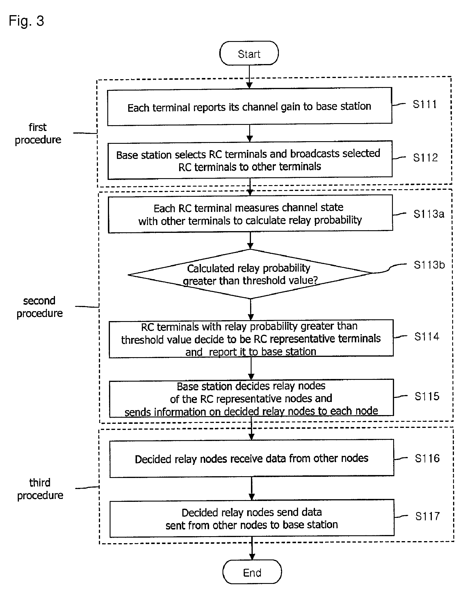
Disclosed is a method for relaying data in a multi-hop cellular system, the method including receiving by a terminal from a base station a notification as to whether the terminal is decided as a candidate for a relay, deciding by the terminal whether to be a representative candidate terminal for the relay according to a channel state with the other terminals within a coverage of the base station if the terminal is decided as the candidate for the relay, sending by the terminal to the base station a notification if the terminal is decided as the representative candidate terminal, and relaying data received from the other terminals to calculate relay probability terminals to the base station if the terminal is notified from the base station as to that the terminal is finally decided as the relay.

Description

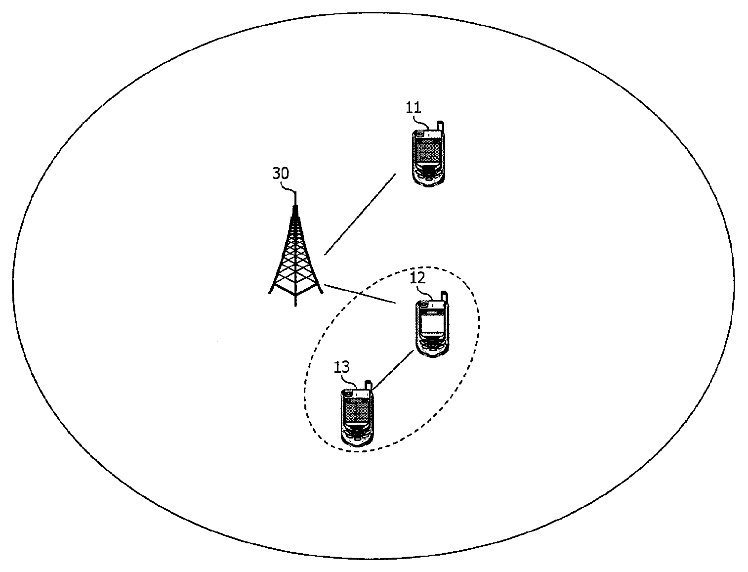
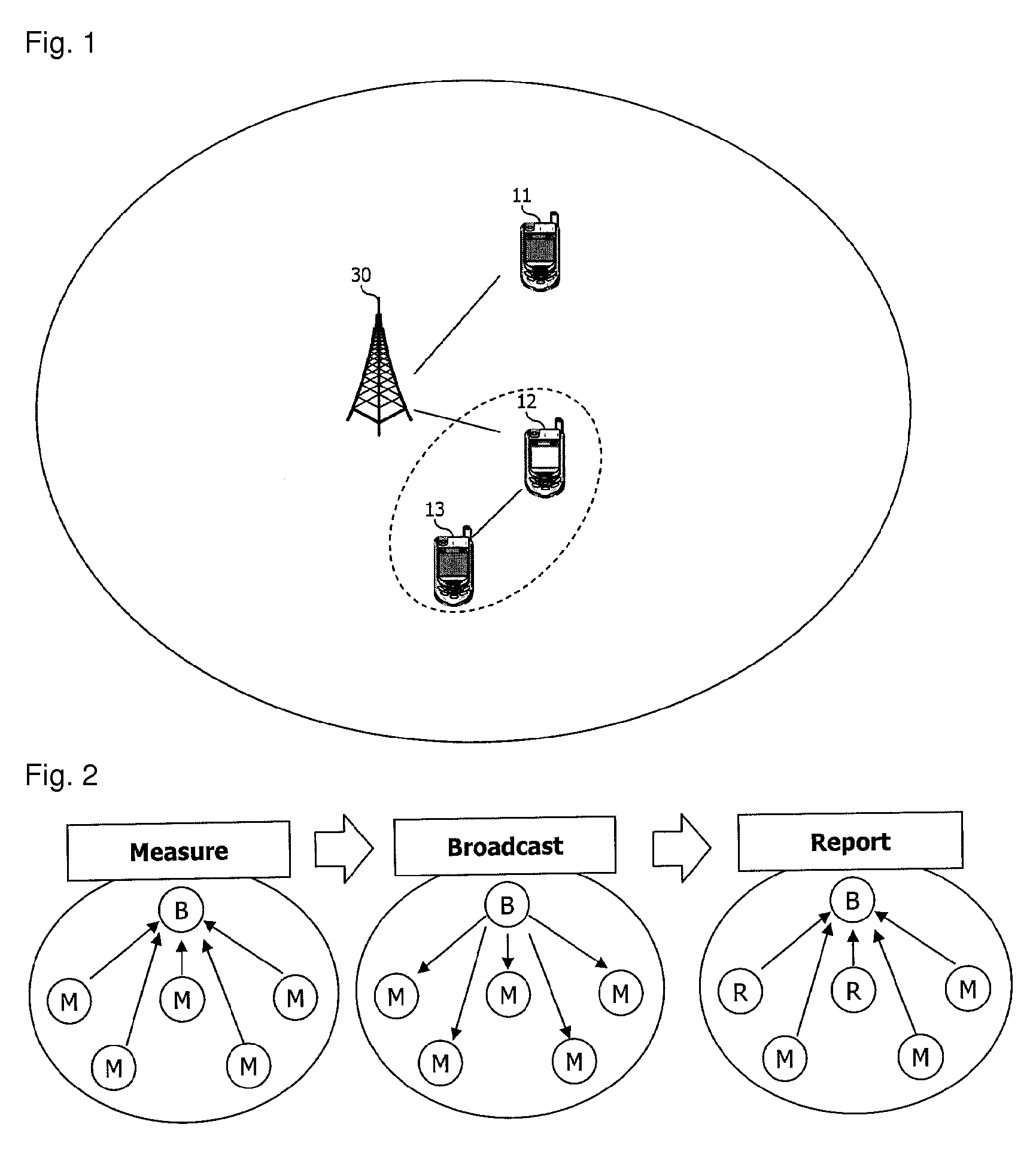
TECHNICAL FIELD[0001]The present invention relates to relaying signals in a multi-hop cellular system.BACKGROUND ART[0002]Many wireless communication technologies have been introduced for high-speed mobile communications.[0003]Cooperatively, cells are getting narrower in radius to support high-speed communications and more telephony communications. Here, it is expected that employment of a centralized architecture using the current wireless network architecture is unable. Accordingly, the next generation communication system should be dispersively controlled and actively deal with environmental changes such as addition of a new base station.[0004]To this end, a multi-hop cellular system has been proposed.[0005]FIG. 1 illustrates a multi-hop cellular system according to the related art.[0006]As shown in FIG. 1, one or more terminals 11, 12 and 13 are present within a coverage area of a base station 30.[0007]Here, one or more specific terminals of the one or more terminals 11, 12 and ...

Claims


Application Information

Patent Timeline
Patent Type & Authority Patents(United States)
IPC IPC(8): H04W40/22H04B7/15H04W40/12H04B17/40
CPCH04W40/22H04W40/12
Inventor YANG, SUCK-CHELKIM, SEONG-LYUNJO, JUN-HOHWANG, YOUNG-JUKO, SEUNG-WOO
Owner IND ACADEMIC COOP FOUND YONSEI UNIV
Why Eureka
Try Eureka