Application of elastomeric vortex generators

a technology of elastomeric vortex and generator, applied in the field of application, can solve the problems of incomplete comparative performance, achieve the effects of improving the cruise performance, improving the flow attachment, and high flap deflection

Inactive Publication Date: 2014-10-28
IRELAND PETER
View PDF39 Cites 40 Cited by
  • Summary
  • Abstract
  • Description
  • Claims
  • Application Information

AI Technical Summary

Benefits of technology

[0089]The use of elastomeric materials allows the designer new freedom to place a flow modifier such as these items in areas that are either sensitive to mass, such as the trailing edge of an aileron or other surface subject to flutter considerations, and in areas where the existing dynamic flexure and torsion of the structure would preclude safety attaching any additional structure which has different material properties to the substrate. This condition also includes cases where the materials may have been common, but the fabrication results in variation of the bending and torsional properties of the flow modifier and the substrate. A particular case in point is attempting to place a transverse device such as a Gurney Flap or Lift Enhancement Tab to the trailing edge of a helicopter rotor, where the attachment base and tab form an L or T form that increases rigidity in an area subject to cyclical bending loads, which cause spanwise distortion of the blade from a straight span. Such application of current art structure of vortex generators would generate high fatigue loads at the bond, resulting in failure or alternatively transfers high loads to the end sections of a strongly bonded / connected tab to blade, where the structural properties of the section with the tab vary from the section without such reinforcement. In the case of a rotor, additionally the increase in rigidity of the trailing edge by the application of a rigid form of tab results in a change in characteristics between the trailing edge bending and the leading edge behavior to these cyclical loads, and results in torsional variations being introduced.
[0099]It is advantageous to have a low density and mass material for a vortex generator applied at or near the rear of a foil section to minimise adverse aeroelastic dynamics.

Problems solved by technology

Testing to date indicates that the vortex generator of multiple blades is effective at developing vortices, however comparative performance is not completed.
Such application of current art structure of vortex generators would generate high fatigue loads at the bond, resulting in failure or alternatively transfers high loads to the end sections of a strongly bonded / connected tab to blade, where the structural properties of the section with the tab vary from the section without such reinforcement.

Method used


Image

  • Application of elastomeric vortex generators
  • Application of elastomeric vortex generators
  • Application of elastomeric vortex generators

Examples


Embodiment Construction

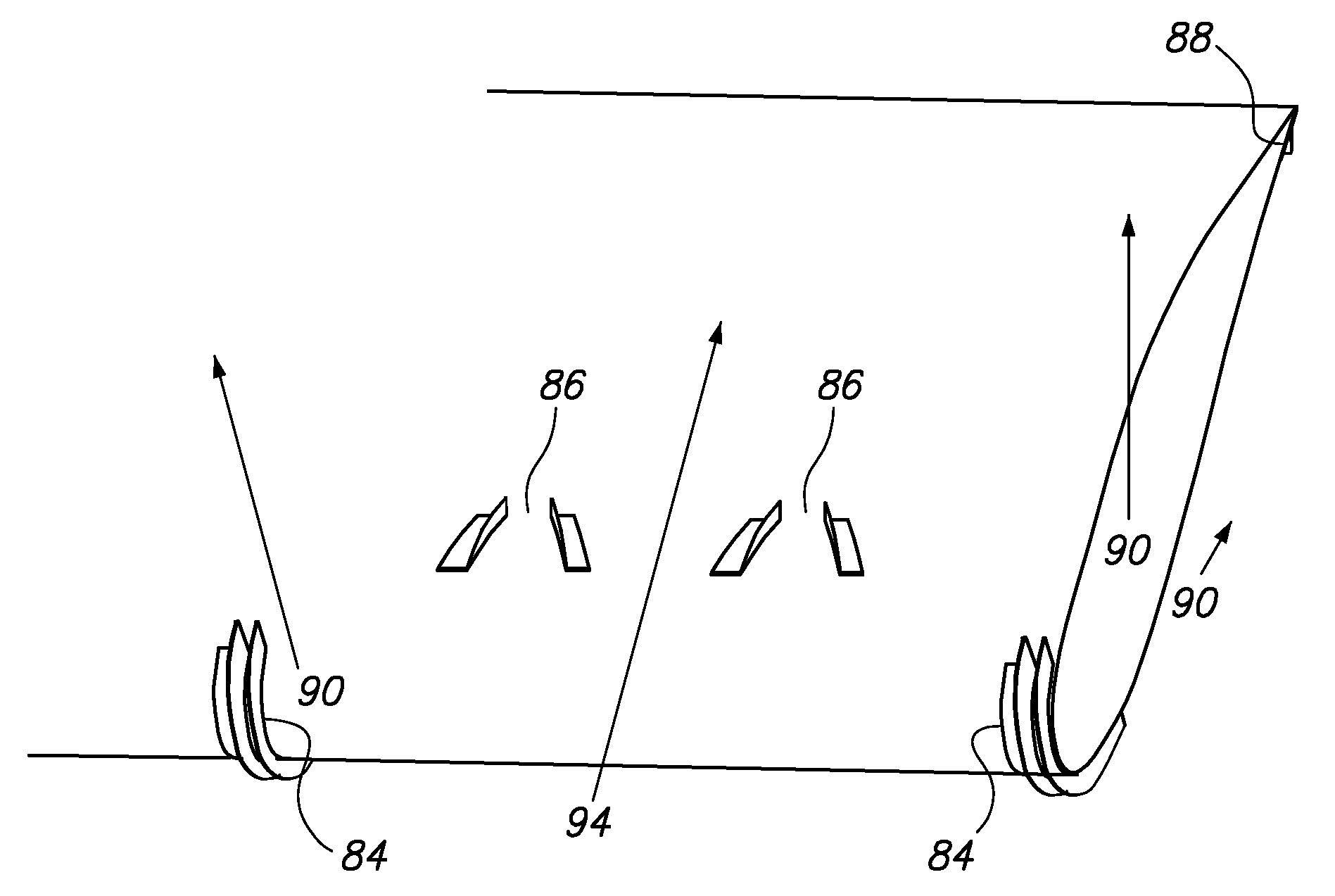
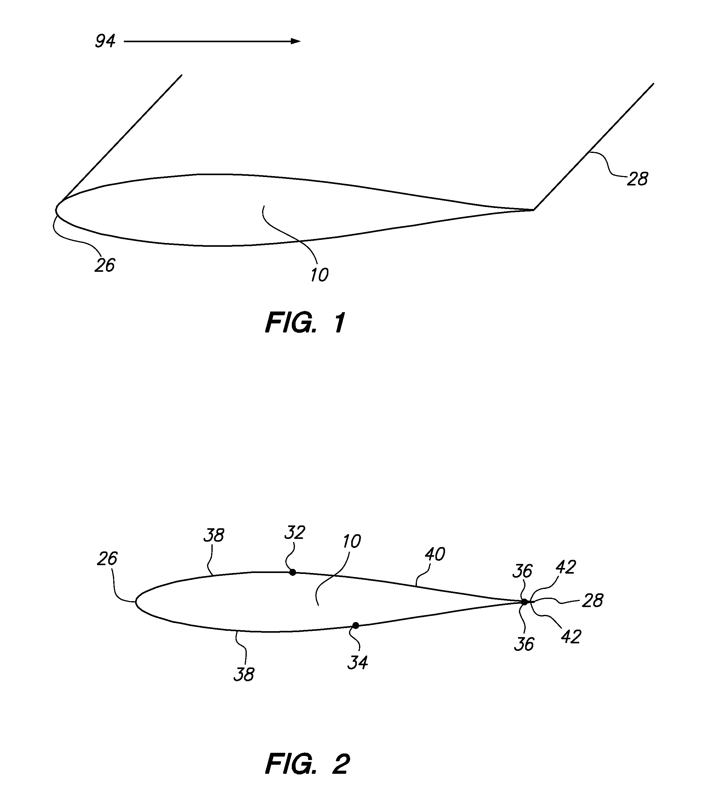
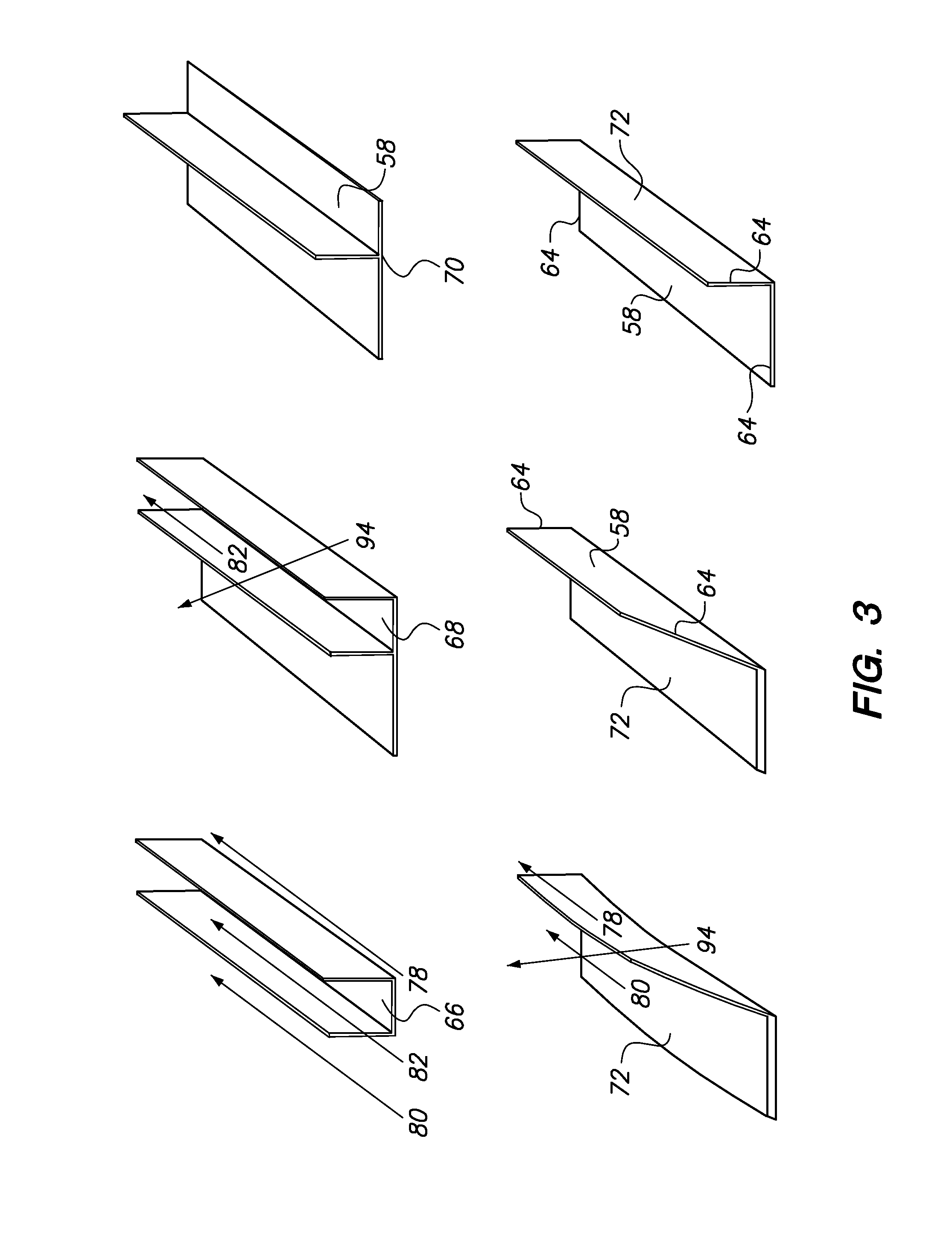
[0113]FIG. 1 is a top perspective view of a generic foil, representation of a foil or aero / hydrodynamic surface 10, showing the general arrangement for the following figures. A foil leading edge 26 is identifiable, as is the foil trailing edge 28. Representative flow directions are shown by annotation with an arrow head, in this case as streamwise flow 94, flowing from left to right in the image. Short streamwise flow 94 or spanwise flow 90 arrows indicate that the flow referred to is on the underside of the image. The arrows for aft face vortice 80, foreward face vortice 78 are indicative only of general flow location, and in the case of a transverse vortex, the direction of the convection of the vortex core is dependent on the incident angle of the streamwise flow 94 and the presence of spanwise flow 90 migration. It is best considered that the rotational flow of the vortex is generally perpendicular to the direction of the vortex arrow, such that the arrow indicates an approximat...


PUM


Abstract

A method of improving aerodynamic performance of foils by the application of conformal, elastomeric vortex generators. The novel use of elastomers allows the application of various forms of vortex generators to sections that have been problematic from engineering and cost considerations. A novel and efficient vortex generator profile is identified, which develops an additional co rotating vortex at low energy expenditure. The mechanisms allow for the application of transverse vortex generators, or Gurney Flaps / Lift Enhancement Tabs / Divergent Trailing Edges, to propellers, rotorblades, and to wings / flaps / control trailing edges. Cove Tabs are additionally described using an elastomeric transverse vortex generator to achieve performance improvements of a high lift device.

Description

RELATED APPLICATIONS[0001]The present application is a continuation-in-part application of U.S. provisional patent application, Ser. No. 61 / 224,481, filed Oct. 7, 2009, for ELASTOMERIC VORTEX GENERATORS, by Peter S. Ireland, included by reference herein and for which benefit of the priority date is hereby claimed.[0002]Elastomeric Vortex Generator Provisional patent, Ireland P S, of August 2009. (EFS ID 5676629 Application Number 61224481 Confirmation Number 2708 Title Elastomeric Vortex Generator(s) First Named Inventor Peter Stephen Ireland)FIELD OF THE INVENTION[0003]The present invention relates to improving foil aerodynamics and, more particularly, to improving lift and drag characteristics. It provides novel material and properties to the field of boundary layer modification and separated flow control, and particularly in the use of blade, ramp, Gurney Flap / Lift Enhancing tab or divergent trailing edge vortex generating systems.BACKGROUND OF THE INVENTION[0004]Performance of a...

Claims


Application Information

Patent Timeline
Patent Type & Authority Patents(United States)
IPC IPC(8): B64C21/10B64C23/06B64C3/14
CPCB64C23/06Y02T50/12B64C23/065Y02T50/164B64C2003/147Y02T50/162Y02T50/10
Inventor IRELAND, PETER
Owner IRELAND PETER
Why Eureka
Try Eureka