Image forming device, and image forming method

a technology of image forming and nozzle, which is applied in the direction of printing, other printing apparatus, etc., can solve the problems of affecting the flow direction of the droplets discharged from the nozzle, clogging of the nozzle, and affecting the nozzle, so as to reduce the running cost, the effect of reducing energy consumption, and reducing the blurring of the droplets of the electrically-conductive recording liquid

Inactive Publication Date: 2014-10-28
RICOH KK
View PDF37 Cites 1 Cited by
  • Summary
  • Abstract
  • Description
  • Claims
  • Application Information

AI Technical Summary

Benefits of technology

[0014]According to the embodiment, the image forming device includes the head having the nozzles that discharge the electrically-conductive recording liquid in accordance with the driving signal; the intermediate transfer body on which the electrically-conductive recording liquid is applied by the head, at least the surface of the intermediate transfer body being electrically conductive; the voltage apply unit that applies the voltage between the intermediate transfer body and the head, so that the electrically-conductive recording liquid is decomposed by the electrolysis, the electrically-conductive recording liquid being discharged from the head and in the state in which the electrically-conductive recording liquid temporarily bridges between the head and the intermediate transfer body; the transfer unit that transfers the image formed of the electrically-conductive recording liquid and supported on the intermediate transfer body onto the recording material; and the discharging control unit that generates the driving signal for discharging the electrically-conductive recording liquid through the nozzles. The discharging control unit in the image forming device generates the driving signal that causes the position of the meniscus to be placed at the outer side of the nozzle, during the formation of the state. Therefore, the image forming device can suppress the blurring of the droplets of the electrically-conductive recording liquid by decomposing the electrically-conductive recording liquid by the electrolysis, while the position of the meniscus is placed at the outer side of the nozzle when the bridge of the electrically-conductive recording liquid is formed. Here, the process liquid or the powders other than the electrically-conductive recording liquid are not added, and the discharging performance of the head to discharge the electrically-conductive recording liquid is ensured. Further, the image forming device can suppress the blurring of the droplets of the electrically-conductive recording liquid by ensuring the decomposition of the electrically-conductive recording liquid by the electrolysis, without utilizing a high voltage or a large amount of electrolytes. Therefore, an image forming device can be provided, which can reduce the energy consumption, the running cost, and the resources. In addition, the image forming device can form high quality images.
[0022]According to the embodiment, in the image forming method, the following units are utilized. Namely, the head having the nozzles that discharge the electrically-conductive recording liquid in accordance with the driving signal; the intermediate transfer body on which the electrically-conductive recording liquid is applied by the head, at least the surface of the intermediate transfer body being electrically conductive; the voltage apply unit that applies the voltage between the intermediate transfer body and the head, so that the electrically-conductive recording liquid is decomposed by the electrolysis, the electrically-conductive recording liquid being discharged from the head and in the state in which the electrically-conductive recording liquid temporarily bridges between the head and the intermediate transfer body; the transfer unit that transfers the image formed of the electrically-conductive recording liquid and supported on the intermediate transfer body onto the recording material; and the discharging control unit that generates the driving signal for discharging the electrically-conductive recording liquid through the nozzles are utilized. Thus the discharging performance of the head to discharge the electrically-conductive recording liquid is ensured and, at the same time, the blurring of the droplets of the electrically-conductive recording liquid is highly suppressed by decomposing the electrically-conductive recording liquid by the electrolysis, in the state in which the position of the meniscus, at the time of forming the bridge with the electrically-conductive recording liquid, is at the outer side of the nozzle, without adding the process liquid or the powders other than the electrically-conductive recording liquid. Further, the blurring of the droplets of the electrically-conductive recording liquid can be suppressed by ensuring the decomposition of the electrically-conductive recording liquid by the electrolysis, without utilizing a high voltage or a large amount of electrolytes. Therefore, an image forming device can be provided, which can reduce the energy consumption, the running cost, and the resources, and which can form high quality images.

Problems solved by technology

When the paper dust adheres to the nozzles, flying directions of the droplets discharged from the nozzles may be perturbed and the nozzles may be clogged.
However, when droplets of the recording liquid having the low viscosity adhere onto the recording material, the droplets tend to be blurred.
Patent Documents 3 and 4), have a problem that the printing speed is reduced due to the adherence of the process liquid or the powders, and a problem that the image forming devices increase in size.
Therefore, the problem that the printing speed is reduced and the problem that the image forming devices increase in size may be required to be resolved, while ensuring the discharging performance of the head to discharge the recording liquid.
However, when a very high voltage is applied between the nozzle and the intermediate transfer body, so as to facilitate the electrolysis, the required power may increase and the recording liquid may be scattered.

Method used


Image

  • Image forming device, and image forming method
  • Image forming device, and image forming method
  • Image forming device, and image forming method

Examples


second embodiment

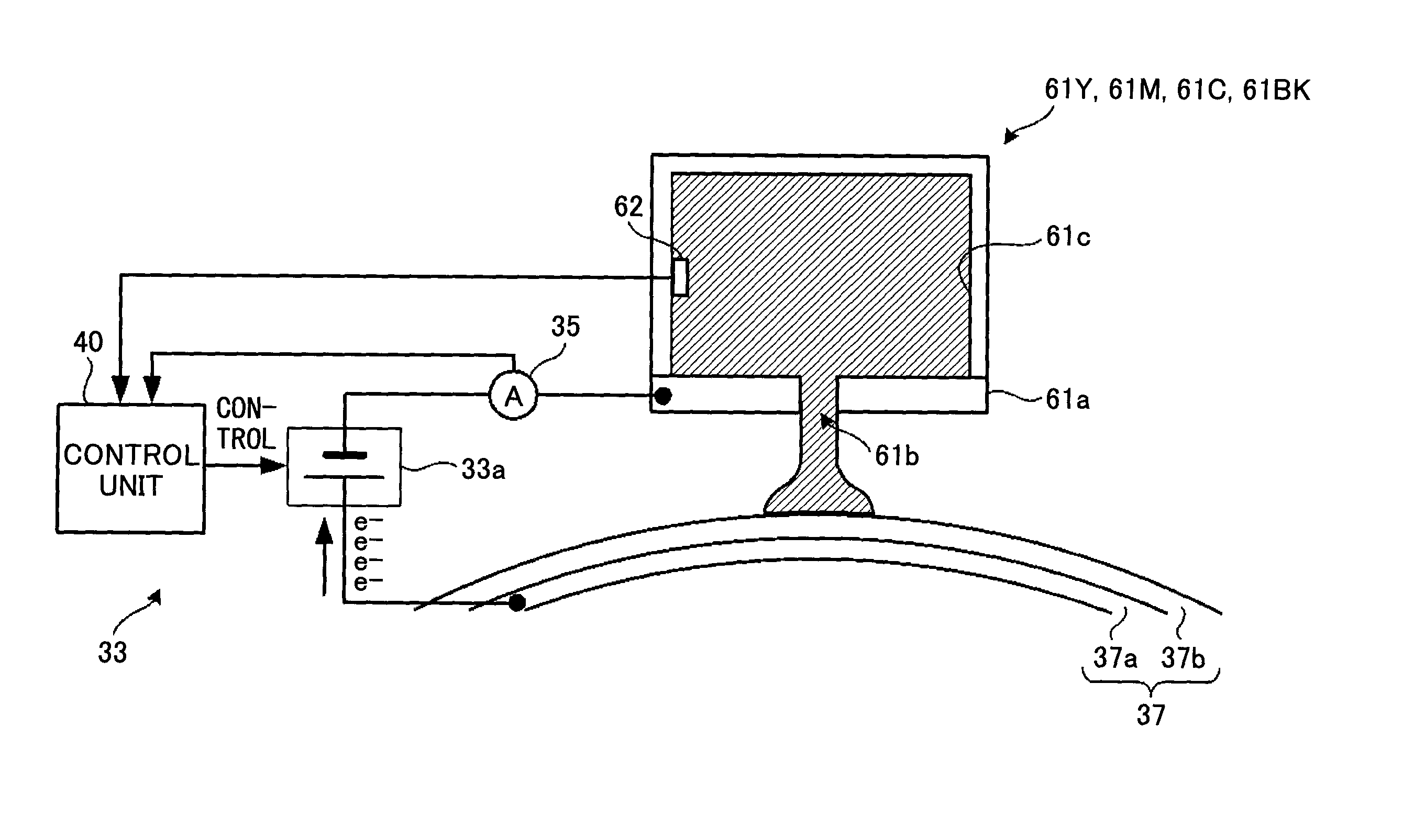
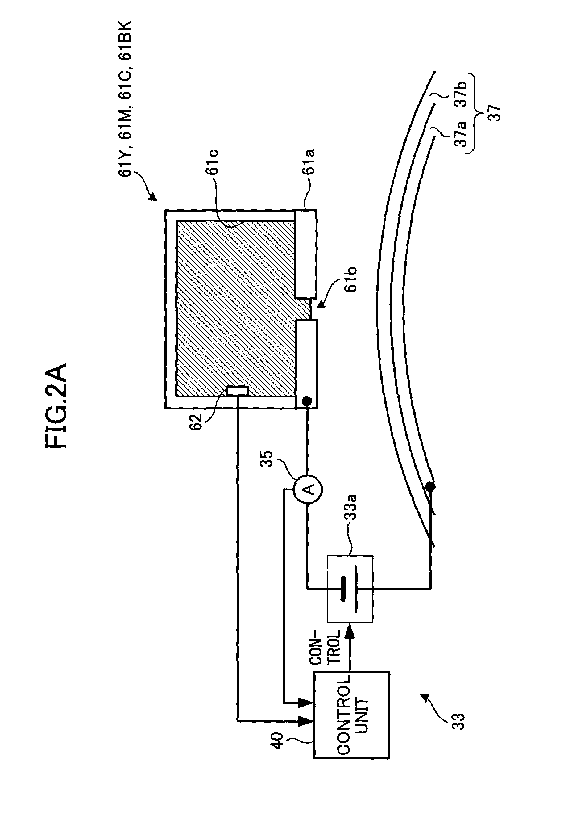
[0193]In a second embodiment, the control unit 40 determines and generates a driving signal in accordance with a table indicating a correspondence between the temperature and the driving signal, which has been prepared in advance and stored in a memory, based on the temperature measured by the temperature sensor 62, in addition to the conditions described in the first embodiment.

[0194]In the second embodiment, the pulse amplitude of the first driving signal and the pulse amplitude of the second driving signal are varied, depending on the measured temperature. Table 2 is the table stored in the memory and indicating the correspondence between the measured temperature and the amplitudes of the first driving signal and the second driving signal.

[0195]Here, the amplitudes of the first driving signal and the amplitudes of the second driving signal are adjusted, so that the discharged volumes and the amounts of the electric charge per unit volume of the recording liquid become substantial...

third embodiment

[0199]In the third embodiment, the control unit 40 determines and generates the driving waveform by using the maximum amount of the current, based on the currents measured with the current sensor 35, in addition to the conditions explained in the first embodiment. The control unit 40 extracts the maximum amount of the current among the electric currents measured by the current sensor 35, during the idle discharging, prior to forming an image. The control unit 40 utilizes the extracted maximum amount of the current, so as to determine the driving signal. Here, the driving signal for performing the idle discharging is the first driving signal with the amplitude of 16 V. The second driving signal is not utilized for the driving signal for performing the idle discharging. The control unit 40 converts the maximum amount of the current into the value per one dot.

[0200]The control unit 40 determines and generates the driving signal in accordance with a table indicating a correspondence bet...


PUM


Abstract

An image forming device includes a head including a nozzle that discharges an electrically-conductive recording liquid in accordance with a driving signal; an intermediate transfer body on which the recording liquid discharged by the head is applied; a voltage apply unit that applies a voltage between the intermediate transfer body and the head, so as to decompose the electrically-conductive recording liquid by electrolysis; a transfer unit that transfers an image supported on the intermediate transfer body onto a recording material; and a discharging control unit that generates the driving signal that causes the electrically-conductive recording liquid to be discharged from the nozzle. The discharging control unit generates the driving signal so that a position of a meniscus is placed outside the nozzle during a time interval in which the recording liquid temporarily bridges between the head and the intermediate transfer body.

Description

TECHNICAL FIELD[0001]Embodiments of the present invention are related to an inkjet image forming device that forms an image by applying a recording liquid, such as ink, onto an intermediate transfer body through a head, and an image forming method using the inkjet image forming device.BACKGROUND ART[0002]An inkjet image forming device, such as an inkjet printer, has conventionally been known, which includes a head that forms and discharges the liquid droplets of a recording liquid, such as ink, through plural microscopic nozzles, based on a method using a movable actuator, such as a piezoelectric method, or a heating film-boiling method, such as a thermal method (cf. Patent Document 1 (Japanese Published Unexamined Application No. H01-130949) and Patent Document 2 (Japanese Registered Patent No. 2724141)), and which performs inkjet recording (cf., Patent Document 3 (Japanese Published Unexamined Application No. 2008-062397), Patent Document 4 (Japanese Published Unexamined Applicati...

Claims


Application Information

Patent Timeline
Patent Type & Authority Patents(United States)
IPC IPC(8): B41J2/045B41J2/005B41J2/06B41J2/385B41J2/115
CPCB41J2/115B41J2/0057B41J2/04563B41J2/3855B41J2/04581B41J2/045B41J2/385
Inventor SUZUKI, RYOTATSUKAMOTO, TAKEOORITO, TAKESHISEO, MANABUSAKUMA, HIDEOMIHASEGAWA, AINOYAMASHITA, HIROYUKIUSUI, YUUMAOHSHIMA, HISAYOSHIMATSUMOTO, TAKAHIKO
Owner RICOH KK
Why Eureka
Try Eureka