
Dual-polarized environmentally-hardened low profile radiating element

Active Publication Date: 2014-10-28
ROCKWELL COLLINS INC
View PDF6 Cites 11 Cited by
  • Summary
  • Abstract
  • Description
  • Claims
  • Application Information

AI Technical Summary

Benefits of technology

The present invention is about a radiating element that can efficiently radiate electromagnetic energy in a specific pattern. The radiating element includes a ground plane layer with slots, a stripline feed layer with vias to promote resonance elimination, a metamaterial layer to promote stability of impedance matching, and a plurality of dipole layers to cancel reflections. The electromagnetic energy is then radiated through the metamaterial layer and the dipole layers to the radome. The technical effect of this invention is to provide a more efficient and stable radiating element for various applications such as radar and communication systems.

Problems solved by technology

A number of currently available radiating elements may not provide a desired level of performance over a desired bandwidth range (ex.—over a broad bandwidth).
For example, currently available radiating elements may suffer a poor match in return loss over a given frequency band, and / or may not provide a desired level of cross-coupling performance over a given frequency band.

Method used


Image

  • Dual-polarized environmentally-hardened low profile radiating element
  • Dual-polarized environmentally-hardened low profile radiating element
  • Dual-polarized environmentally-hardened low profile radiating element

Examples


Embodiment Construction

[0015]Reference will now be made in detail to the presently preferred embodiments of the invention, examples of which are illustrated in the accompanying drawings.

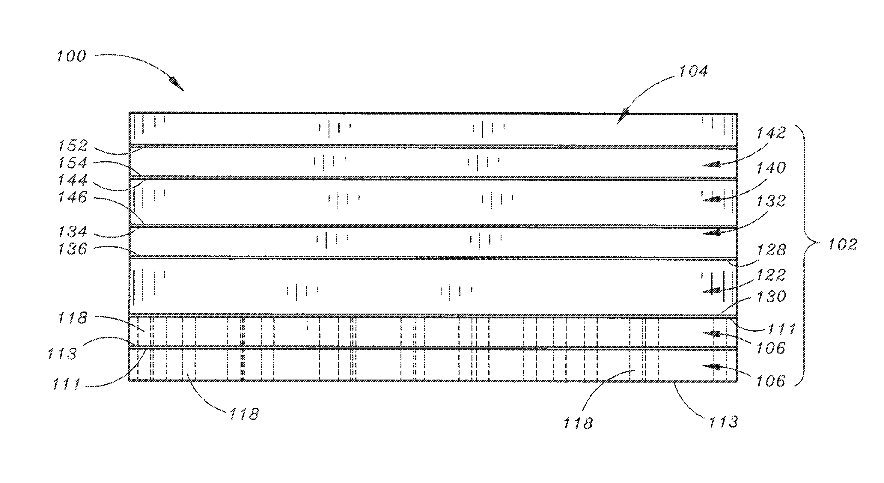
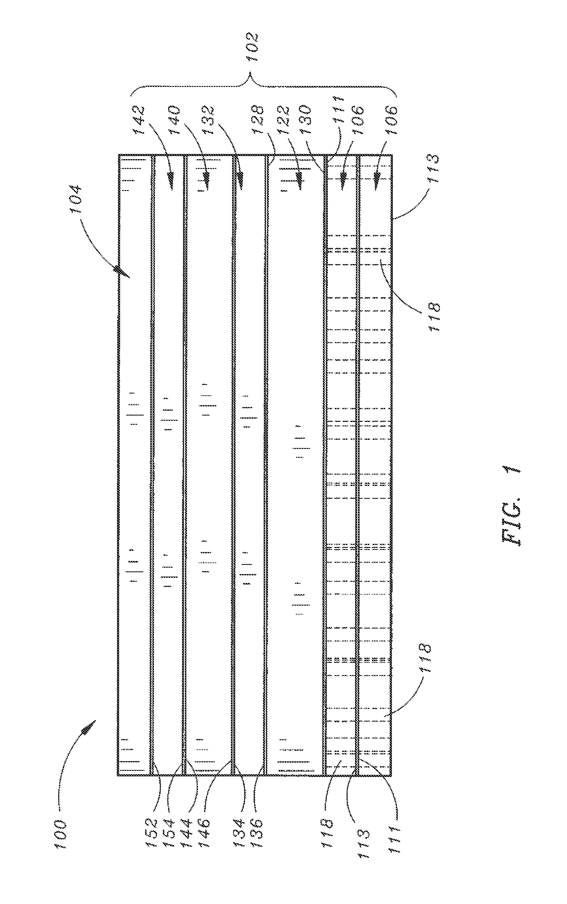
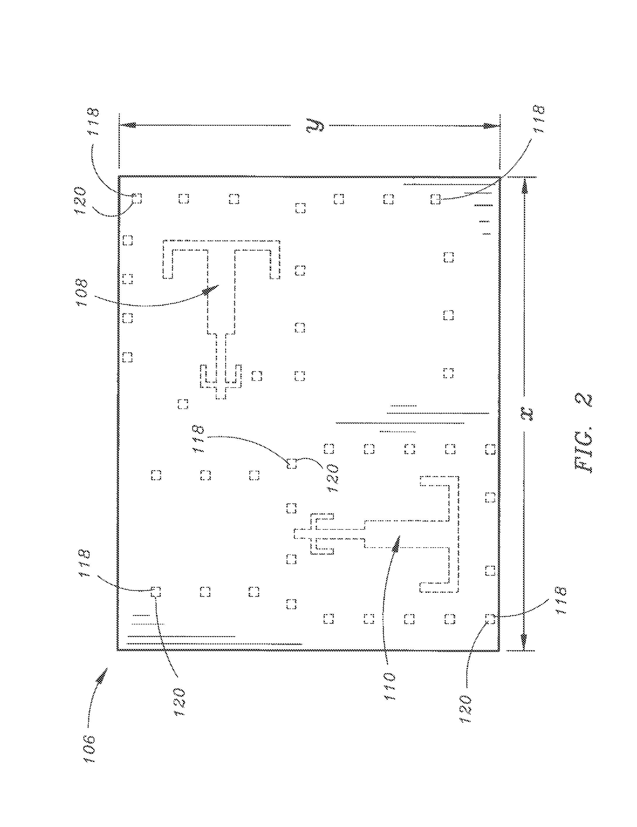
[0016]Referring to FIG. 1, a radiating element assembly in accordance with an exemplary embodiment of the present invention is shown. In an exemplary embodiment of the present invention, the radiating element assembly 100 may include a radiating element 102. In further embodiments of the present invention, the radiating element assembly 100 may further include a radome 104. In current exemplary embodiments of the present invention, the radome 104 may be configured for being connected to (ex.—integrated with) the radiating element assembly. In further embodiments of the present invention, the radome 104 may be constructed of printed circuit board material(s), dielectric materials, laminate material(s) and / or bonding material(s) (ex.—Arlon CLTE™ core(s)). In still further embodiments of the present invention, the radome 104 ...


PUM


Abstract

The present invention is directed to a radiating element assembly including radiating element integrated with a radome. The radiating element assembly may be dual-polarized. Further, the radiating element assembly may operate over a frequency band of 10.9 GHz-14.5 GHz and may be configured for minimizing polarization cross-talk at Array Normal Scan of well below −30 decibels over the entire frequency band. Still further, the radiating element assembly may provide return loss at Array Normal Scan of less than or equal to −10 dB.

Description

FIELD OF THE INVENTION[0001]The present invention relates to the field of antennas and more particularly to a dual-polarized environmentally-hardened low profile radiating element.BACKGROUND OF THE INVENTION[0002]A number of currently available radiating elements may not provide a desired level of performance over a desired bandwidth range (ex.—over a broad bandwidth). For example, currently available radiating elements may suffer a poor match in return loss over a given frequency band, and / or may not provide a desired level of cross-coupling performance over a given frequency band.[0003]Thus, it would be desirable to have a radiating element which addresses the problems associated with currently available solutions.SUMMARY OF THE INVENTION[0004]Accordingly an embodiment of the present invention is directed to a radiating element, including: a ground plane layer, the ground plane layer having a first slot and a second slot formed therethrough; a stripline feed layer, the stripline f...

Claims


Application Information

Patent Timeline
IPC IPC(8): H01Q13/10
CPCH01Q13/10H01Q9/285H01Q15/0086H01Q1/405H01Q9/06
Inventor BUCKLEY, MICHAEL J.HERTING, BRIAN J.MATHER, JOHN C.EL SALLAL, WAJIH A.
Owner ROCKWELL COLLINS INC
Learn More