Drone for inspection of enclosed space and method thereof

a drone and enclosed space technology, applied in the direction of television systems, distance measurement, instruments, etc., can solve the problems of loss of time of operation of the turbine associated with the boiler being inspected, inconvenience for inspectors, and laborious processes

Inactive Publication Date: 2014-10-28
UNITED DYNAMICS ADVANCED TECH
View PDF48 Cites 122 Cited by
  • Summary
  • Abstract
  • Description
  • Claims
  • Application Information

AI Technical Summary

Benefits of technology

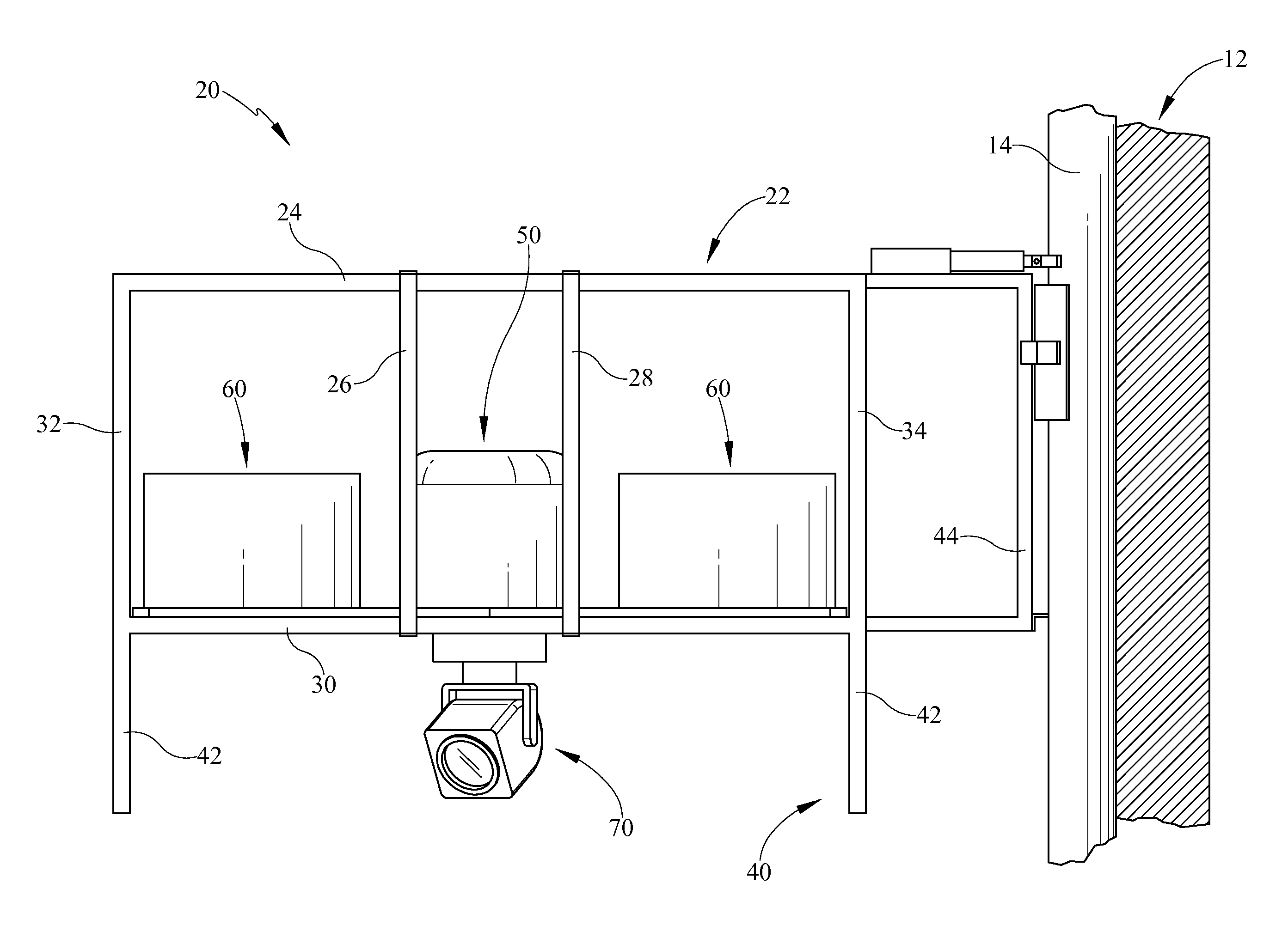
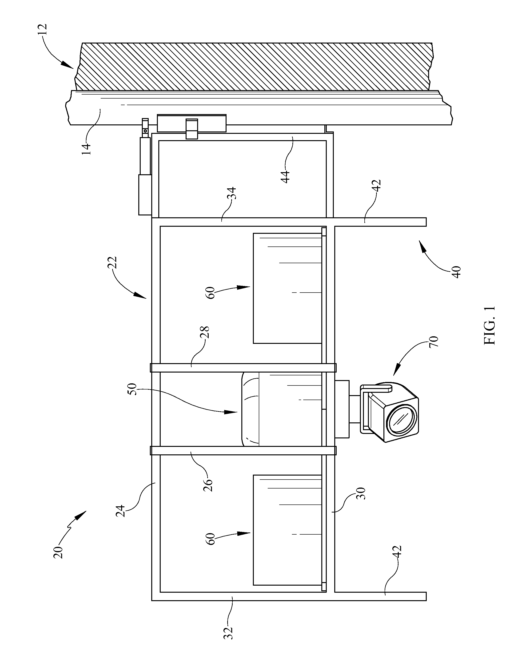
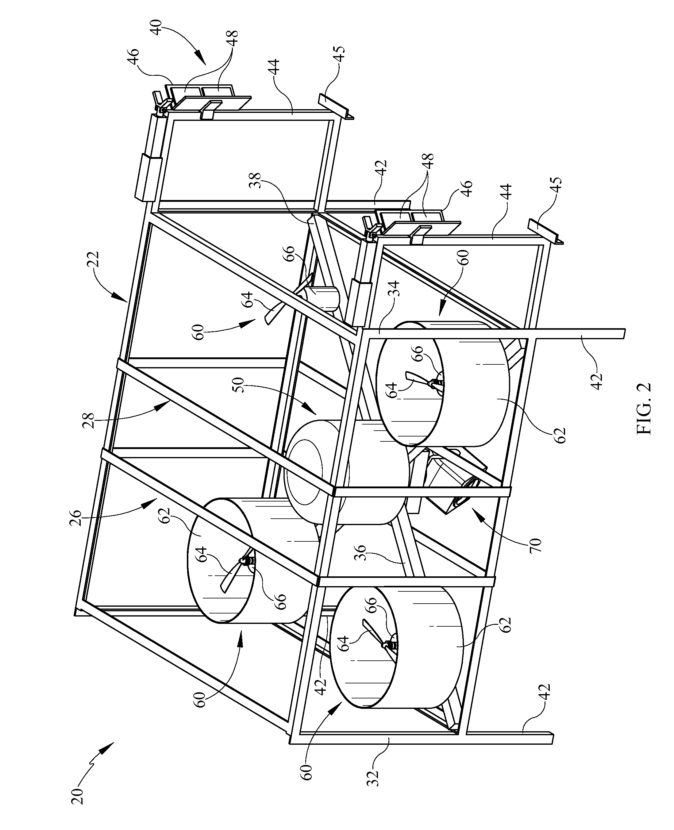
[0011]According to some embodiments, an unmanned remote control inspection vehicle, comprises an airframe including at least one propulsion assembly, a video camera allowing for pivotal movement, a video transmitter, a controller with flight avionics to control the at least one propulsion assembly, a transceiver in communication with the controller and a remote control, a landing assembly connected to the airframe, the landing assembly having at least one support structure for landing in a first orientation and at least one second support structure for landing in a second orientation, a detaching mechanism to release the landing assembly from a surface in one of the first and second orientations. The unmanned remote control inspection vehicle wherein the landing assembly has the at least one support structure being generally horizontal in orientation. The unmanned remote control inspection vehicle wherein the landing assembly has the at least one second support structure being generally vertical in orientation. The unmanned remote control inspection vehicle wherein the landing assembly includes a landing frame having a first strut and a second strut. The unmanned remote control inspection vehicle wherein the landing assembly includes a third and a fourth strut. The unmanned remote control inspection vehicle further comprising a retaining mechanism one of the at least one first and second support mechanism for landing in a vertical orientation. The unmanned remote control inspection vehicle wherein the retaining mechanism has magnetic landing feet. The unmanned remote control inspection vehicle wherein the magnetic feet are pivotable about a vertical axis. The unmanned remote control inspection vehicle wherein the magnetic feet are movable to change width between said landing feet.
[0012]According to an alternate embodiment, an unmanned remote control inspection vehicle, comprises an airframe including a plurality of propulsion assemblies, a controller in communication with the plurality of propulsion assemblies, a remote control in wireless communication with the controller to control flight of the vehicle, a landing structure connected to the airframe, the landing structure allowing landing on a surface parallel to a gravity force, the landing structure allowing landing on a surface perpendicular to a gravity force, a retaining mechanism on the landing structure and a detachment mechanism, a video camera onboard the vehicle for inspection. The unmanned remote control inspection vehicle wherein the retaining mechanism is magnetic. The unmanned remote control inspection vehicle wherein the detachment mechanism is a linear actuator. The unmanned remote control inspection vehicle wherein the landing structure has at least one strut in vertical orientation and at least one strut in a horizontal direction. The unmanned remote control inspection vehicle further comprising a receiver for electronic communication between the remote control and the controller. The unmanned remote control inspection vehicle wherein the video camera is mounted on a gimbal allowing at least one degree of pivot.
[0013]According to at least one further embodiment, an unmanned remote control inspection vehicle, comprises an airframe having at least one propulsion assembly, a controller in electrical communication with the at least one propulsion assembly, a receiver in communication with the controller, the receiver in wireless communication with a remote control, at least one camera for video inspection and non-line-of-flight of the vehicle, a landing structure connected to the airframe, the landing structure having a first portion defining a first outer boundary of the vehicle along a first dimensional axis and a second portion defining a second outer boundary of the vehicle along a second dimensional axis. The vehicle further comprising a rechargeable battery. The vehicle wherein the propulsion assembly includes an electric motor. The vehicle wherein the at least one camera is an inspection camera. The vehicle wherein the at least one camera includes a pilot camera.
[0014]According to some embodiments, a method of inspecting a boiler, comprises positioning a remote control unmanned aircraft adjacent an enclosed space, flying the aircraft within the enclosed space, flying to a first position, landing the aircraft on one of a vertical sidewall or vertical steam piping within the boiler, scanning an area of the enclosed space with a video camera, powering up a propulsion assembly, detaching the vehicle from the one of a vertical sidewall or vertical steam piping within the boiler, flying the aircraft to a second position. The method further comprises flying by line of sight. The method further comprises flying by video from the video camera. The method further comprising a sending an acoustic signal toward a wall of the enclosed space to locate the aircraft. The method further comprises engaging the one of a vertical sidewall or vertical steam piping with a magnet on a landing assembly. The method further comprises recording video on the aircraft. The method further comprises wirelessly transmitting a video signal from the camera to a control station. The method further comprises recording a video signal at a control station. The method further comprises viewing video in real-time at a control station.
[0015]According to some other embodiments, a method of boiler inspection with an unmanned remote control aircraft, comprises establishing a control area for flying said aircraft, flying the aircraft within the boiler, transmitting video of the flight to the control area for guiding said aircraft, guiding the aircraft to a generally vertical landing position, landing the aircraft at the generally vertical landing position, powering down at least one propulsion assembly, scanning an area of the boiler with a camera, recording video of the scanning, detaching the aircraft from the generally vertical landing position; flying to a second landing position and, landing at said second landing position. The method further comprises powering up the at least one propulsion assembly. The method wherein the recording occurs on-board said aircraft. The method wherein the recording occurs at the control area. The method further comprises powering up the at least one propulsion assembly. The method further comprises scanning an area at the second landing area of the boiler. The method further comprises actuating an actuator to perform the detaching. The method further comprises depowering magnets to perform the detaching. The method further comprises adjusting feet for the landing. The method further comprises adjusting at least one of width, pivot about a vertical axis and pivot about a horizontal axis.

Problems solved by technology

The process of inspecting enclosed spaces, for example such as a boiler of a power generating turbine, is a process which is tedious, labor intensive, and provides opportunity for injury to an inspector.
This requires manpower and downtime of the boiler both of which result in lost time of operation of the turbine associated with the boiler being inspected.
However, this construction process takes time again leading to increased outage time for the boiler.
An additional problem with inspection of the enclosed space is that the walls are generally vertical and are lined with steam tubing and / or burners along the interior surface thereof in large part.

Method used


Image

  • Drone for inspection of enclosed space and method thereof
  • Drone for inspection of enclosed space and method thereof
  • Drone for inspection of enclosed space and method thereof

Examples


Embodiment Construction

[0033]It is to be understood that the inspection drone with vertical attachment mechanism is not limited in its application to the details of construction and the arrangement of components set forth in the following description or illustrated in the drawings. The invention is capable of other embodiments and of being practiced or of being carried out in various ways. Also, it is to be understood that the phraseology and terminology used herein is for the purpose of description and should not be regarded as limiting. The use of “including,”“comprising,” or “having” and variations thereof herein is meant to encompass the items listed thereafter and equivalents thereof as well as additional items. Unless limited otherwise, the terms “connected,”“coupled,” and “mounted,” and variations thereof herein are used broadly and encompass direct and indirect connections, couplings, and mountings. In addition, the terms “connected” and “coupled” and variations thereof are not restricted to physi...


PUM


Abstract

Embodiments of a drone for inspection and a method of use are depicted wherein the drone is utilized in an enclosed space and is capable of being controlled with or without line of sight to the aircraft. The drone may land on generally horizontal or vertical surfaces. A method of use is taught as well.

Description

STATEMENT REGARDING FEDERALLY SPONSORED RESEARCH[0001]None.REFERENCE TO SEQUENTIAL LISTING, ETC.[0002]None.CLAIM TO PRIORITY[0003]None.BACKGROUND[0004]1. Field of the Invention[0005]Present embodiments relate to a drone device. More specifically, present embodiments relate to a drone for inspection of an enclosed space and a method thereof.[0006]2. Description of the Related Art[0007]The process of inspecting enclosed spaces, for example such as a boiler of a power generating turbine, is a process which is tedious, labor intensive, and provides opportunity for injury to an inspector. During the process, a scaffold must be constructed within the interior of the boiler and along the wall perimeter of the enclosed space to inspect the burners, steam piping or tubing at multiple elevations. As a result, the scaffold must be constructed level by level upon itself to move up along the sidewalls of the enclosed space for inspection of all the boiler walls or steam tubes. This requires manp...

Claims


Application Information

Patent Timeline
Patent Type & Authority Patents(United States)
IPC IPC(8): B64C19/00G05D1/00B64D47/08B64D31/06
CPCB64C19/00B64D47/08B64D31/06B64C2201/042B64C2201/127B64C39/024F22B21/00B64C2201/108B64C2201/027F22B37/00B64U10/13B64U30/20B64U50/19B64U2101/30H04N23/66H04N23/555B64U2201/20G05D1/0038H04N5/76H04N7/185
Inventor CAVOTE, JOHN, M.
Owner UNITED DYNAMICS ADVANCED TECH
Why Eureka
Try Eureka