Solar array system for covering a body of water

a solar array and water body technology, applied in the field of solar panels, to achieve the effect of facilitating installation of very large solar panel arrays, reducing evaporation, and saving water

Inactive Publication Date: 2014-11-04
P4P HLDG
View PDF143 Cites 12 Cited by
  • Summary
  • Abstract
  • Description
  • Claims
  • Application Information

AI Technical Summary

Benefits of technology

[0010]The present invention provides solar panel arrays that are used to simultaneously capture solar energy for producing power and for solar panels incorporated within arrays that cover a body of water to reduce evaporation thereby conserving water. In one preferred embodiment of the invention, it includes a solar panel array installed over a body of water, such as a canal or aqueduct. The underlying support structure for supporting the solar panels can be generally characterized as a cable truss construction that spans the body of water, and is anchored on opposite sides of the body of water by columns and cable tie downs or anchors. Canals / aqueducts typically have generally parallel extending opposing banks. This geometry of this type of waterway facilitates installation of very large solar panel arrays with repeated truss structures spaced longitudinally from one another along the length of the arrays.
[0011]Each of the trusses includes a plurality of supporting members that provide a continuous supporting frame to support mounting of a plurality of solar panels. Direct support for the solar panels is provided by a plurality of panel receivers or pods that are mounted to the corresponding trusses. The particular arrangement of the members of the cable trusses including both tension and compression members provides for a very light, yet structurally robust construction that can withstand significant loading conditions. Particularly for long, continuous spans of a solar array, wind loads can present significant problems, and the solar array must therefore be able to withstand significant wind loading conditions. The present invention provides a solution to withstand difficult loading conditions, yet with a design that is economical and easy to install.

Problems solved by technology

Particularly for long, continuous spans of a solar array, wind loads can present significant problems, and the solar array must therefore be able to withstand significant wind loading conditions.

Method used


Image

  • Solar array system for covering a body of water
  • Solar array system for covering a body of water
  • Solar array system for covering a body of water

Examples


Embodiment Construction

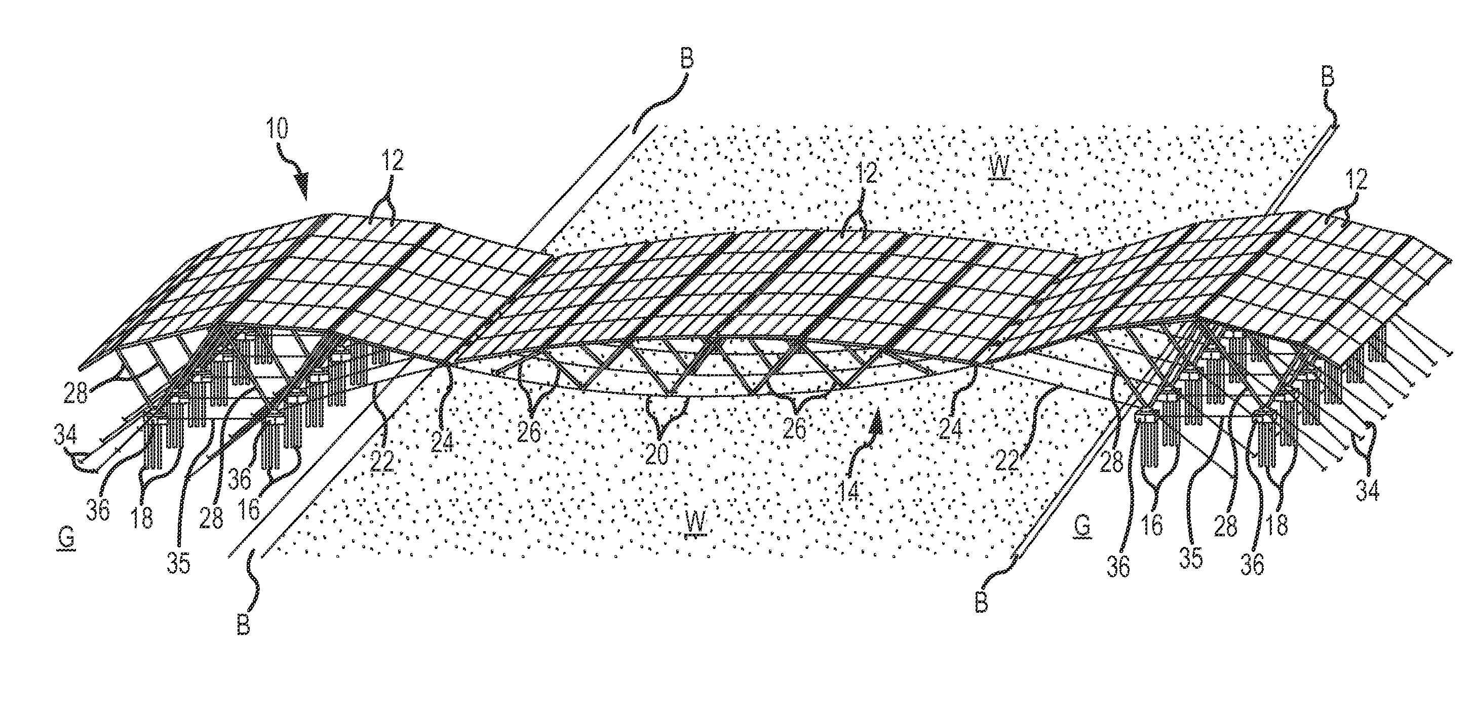
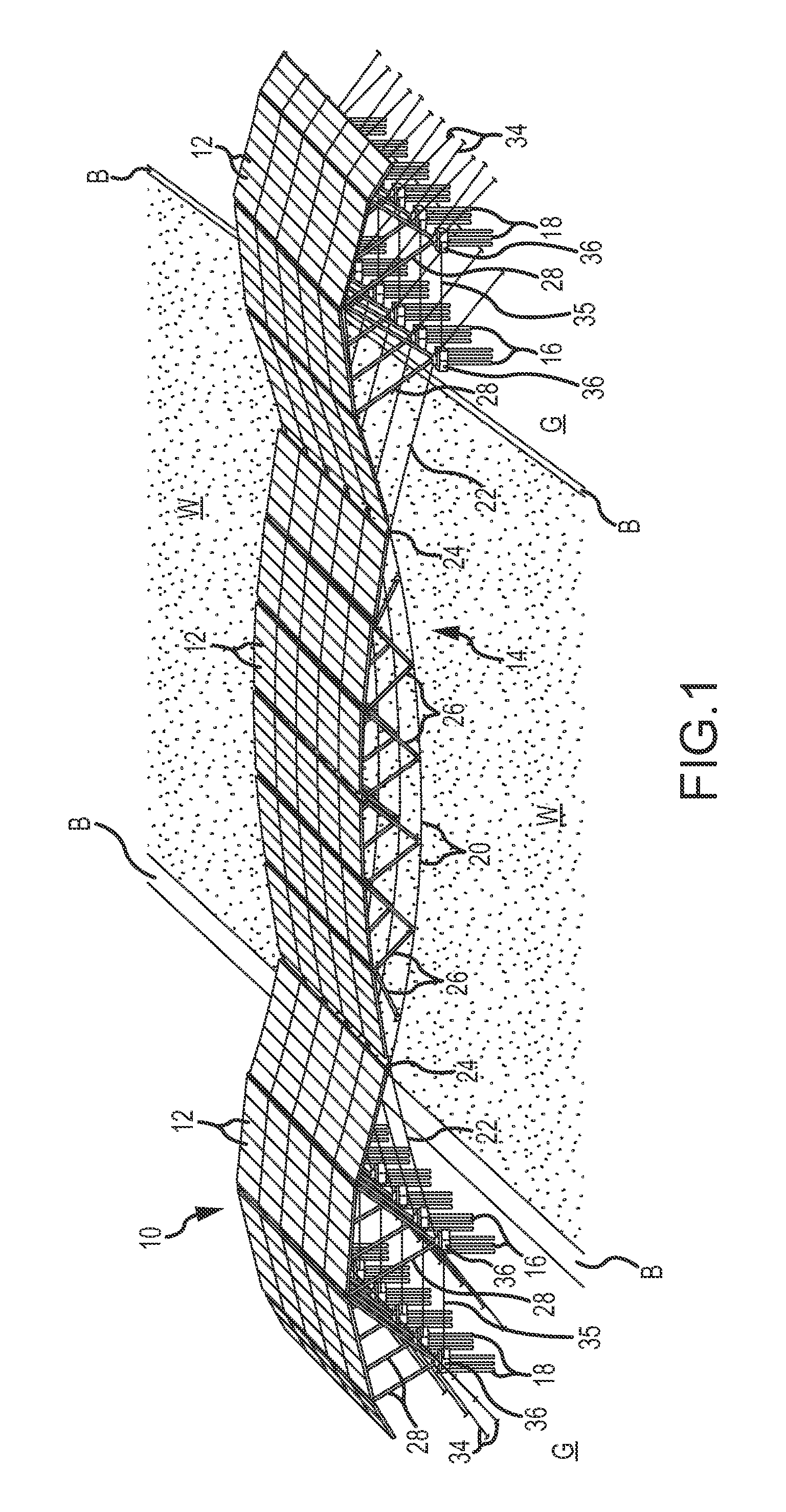
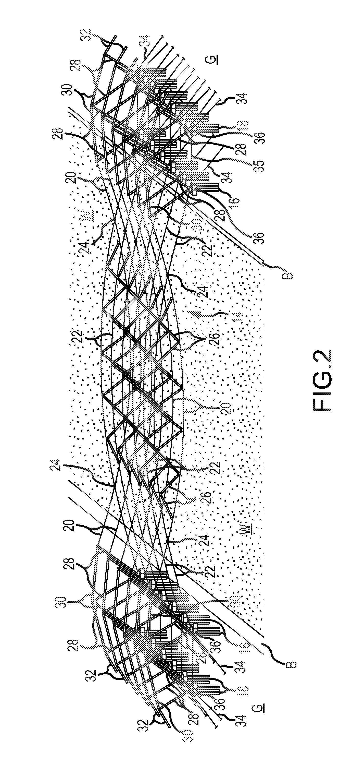
[0039]Referring to FIGS. 1, 2, 2A and 2B, a solar panel array 10 is illustrated in a first embodiment. The array 10 spans a body of water W, such as a canal or aqueduct. The body water W is shown as having two generally parallel extending banks B. Although the solar panel array 10 is especially adapted for installation over long stretches of bodies of water with generally parallel banks, it shall be understood that the array 10 is not limited to any particular configuration for a body of water. A length of the array can be defined as the length that the array extends along opposing banks of the body of water W. A width of the array can be defined as the distance between the banks.

[0040]The solar panel array 10 includes primary groups or assemblies including (i) a plurality of solar panels 12, (ii) a plurality of cable truss assemblies 14 that are spaced from one another along a length of the array, and (iii) a plurality of support columns or similar ground mounted structures that su...


PUM


Abstract

Systems and methods for supporting a solar panel array are disclosed, with embodiments specifically directed to spanning bodies of water such as aqueducts, canals, or other waterways. Cable truss assemblies are used to support panel receivers and solar panels mounted over the panel receivers. The cable truss assemblies are supported on groups of columns or other vertically extending support members anchored in the ground. Cable anchor lines may supplement anchoring and support of the installed solar panel array. Embodiments of the system include various combinations of supporting cables making up the cable truss assemblies. A method is also provided for construction of the solar panel array. Lengthy and continuous spans of the solar panel array can be installed over waterways by use of the cable truss assemblies. The solar panel arrays produce power, and simultaneously reduce evaporation from the waterways, resulting in conservation of water.

Description

CROSS REFERENCE TO RELATED APPLICATIONS[0001]This application is a continuation-in-part of U.S. application Ser. No. 12 / 817,063 entitled: “Solar Array Support Methods and Systems”, filed on Jun. 16, 2010, which is a continuation-in-part of U.S. application Ser. No. 12 / 580,170 entitled: “Solar Array Support Methods and Systems”, filed on Oct. 15, 2009, which is a continuation-in-part application of U.S. application Ser. No. 12 / 466,331, filed on May 14, 2009 entitled “Solar Array Support Methods and Systems, which is a continuation-in-part application of U.S. application Ser. No. 12 / 255,178, filed on Oct. 21, 2008 entitled “Solar Array Support Methods and Systems”, now U.S. Pat. No. 8,212,140, which is a continuation-in-part application of U.S. application Ser. No. 12 / 143,624, filed on Jun. 20, 2008 entitled, “Solar Array Support Methods and Systems”, now U.S. Pat. No. 8,278,547, which is a continuation-in-part application of U.S. application Ser. No. 12 / 122,228, filed on May 16, 2008...

Claims


Application Information

Patent Timeline
Patent Type & Authority Patents(United States)
IPC IPC(8): H01L31/042F24J2/52E04H12/20
CPCF24J2/5241F24J2/523Y02E10/50H01L31/0422Y02E10/47H01L31/042E02B5/00E04H4/10F24J2/51F24J2002/5281H02S20/00H02S20/10H02S30/00E02B1/00F24S25/10F24S25/50F24S2025/014F24S80/60
Inventor CONGER, STEVEN, J.
Owner P4P HLDG
Why Eureka
Try Eureka