Oil storage tank and construction vehicle

a technology for oil storage tanks and construction vehicles, which is applied in the direction of tank vehicles, transportation and packaging, transportation items, etc., can solve the problems of increasing the overall space for disposing of oil storage tanks, gravel and/or dust are liable to penetrate the interior of hydraulic oil tanks through the breather valve, and workers may have difficulty in gaining etc., to achieve the effect of improving the footing on the step

Active Publication Date: 2014-11-04
KOMATSU LTD
View PDF17 Cites 4 Cited by
  • Summary
  • Abstract
  • Description
  • Claims
  • Application Information

AI Technical Summary

Benefits of technology

[0057]In accordance with the present invention, it is possible to provide an oil storage tank that can improve footing on the step, and to provide a construction vehicle comprising the oil storage tank.

Problems solved by technology

There is accordingly a problem in that the worker may have difficulty gaining footing on the step.
However, with such techniques, gravel and / or dust are liable to penetrate the interior of the hydraulic oil tank via the breather valve.
However, there is a problem with such a technique in that the space for drawing the breather hose around must be obtained in the vicinity of the hydraulic oil tank, and the space for disposing the oil storage tank overall increases.

Method used


Image

  • Oil storage tank and construction vehicle
  • Oil storage tank and construction vehicle
  • Oil storage tank and construction vehicle

Examples


first embodiment

Modification of First Embodiment

[0120]The present invention is described by the first embodiment above, but the statements and drawings constituting a portion of this disclosure should not be construed as a limitation of the invention. Various alternate embodiments, examples, and operational techniques are apparent from this disclosure to a person skilled in the art.

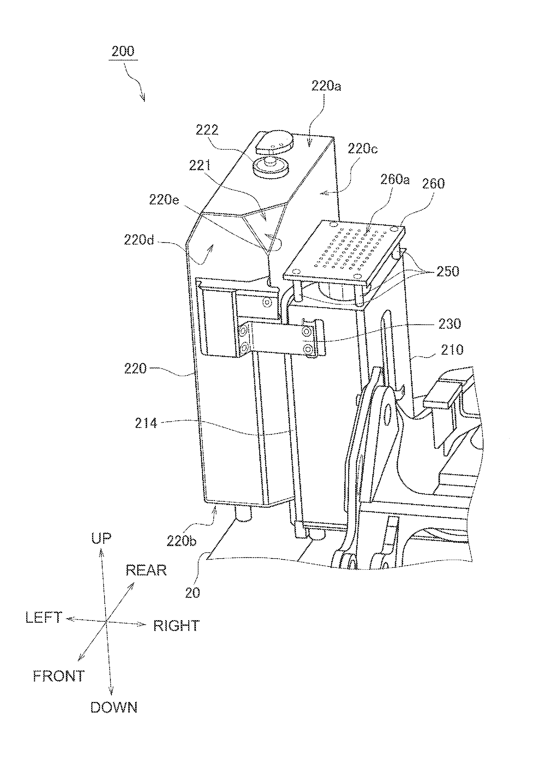
[0121]In the first embodiment, a recessed section 221 communicates with the upper face 220a and the lower face 220b, but no limitation is imposed thereby. The recessed section 221 may be formed by providing the sloped face 220e to a corner portion of the upper face 220a, the first side face 220c, and the second side face 220d, as shown in FIG. 6, and is not required to communicate to the lower face 220b.

[0122]In the first embodiment, the step 260 has an elongated portion 262 that is elongated into the recessed section 221, but no limitation is imposed thereby. The step 260 is not required to have an elongated portion 26...

second embodiment

[0126]A second embodiment of the present invention is described below with reference to the drawings. However, the configuration of the hydraulic excavator 100 is the same as that of the first embodiment, and the description wilt therefore begin with the internal configuration of the hydraulic excavator 100.

Internal Configuration of Construction Vehicle

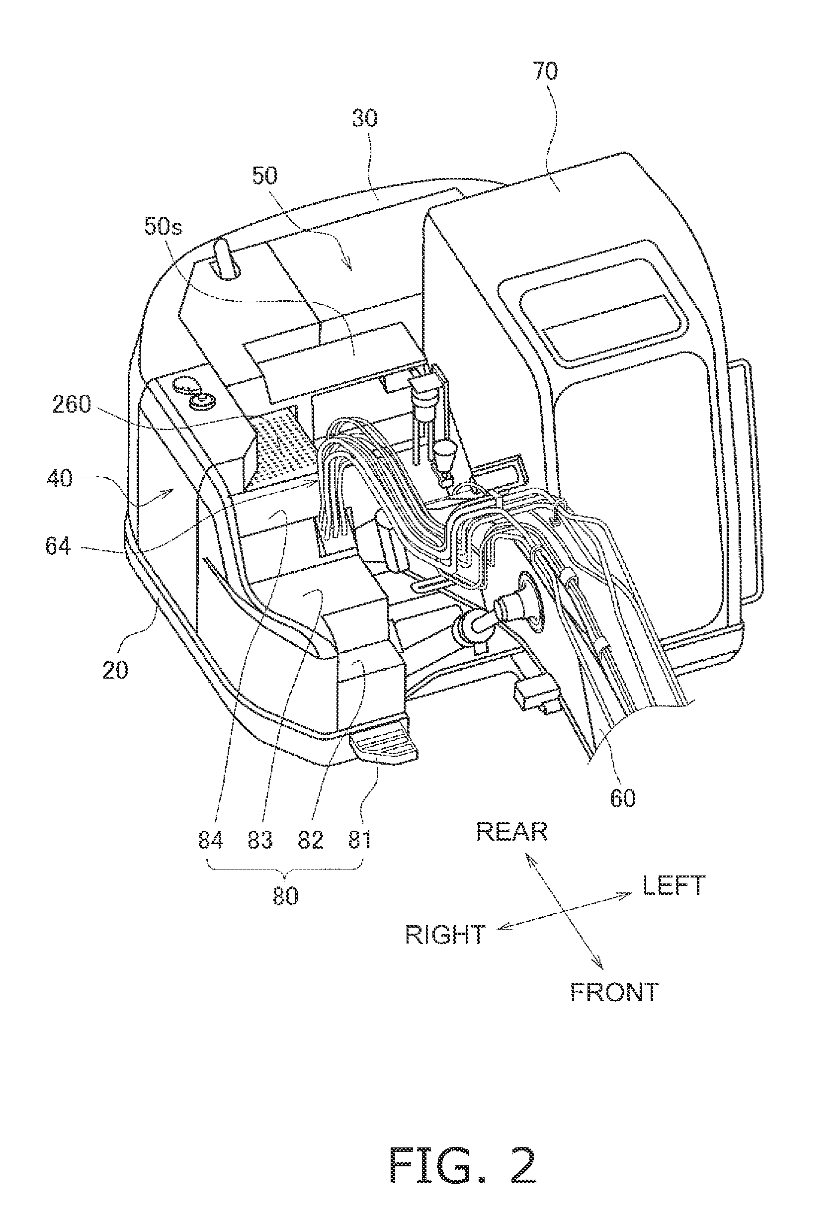
[0127]First, the internal configuration of the construction vehicle 100 according to the second embodiment will be described with reference to the drawings. FIG. 9 is a perspective view showing the internal configuration of the hydraulic excavator 100 according to the second embodiment. FIG. 10 is a plan view showing the internal configuration of the hydraulic excavator 100 according to the second embodiment.

[0128]The oil storage tank 200 disposed on the swivel platform 20 is accommodated in the machine compartment 40. The oil storage tank 200 has a hydraulic oil tank 210 and a fuel oil tank 220. The hydraulic oil tank 210 is disposed...


PUM


Abstract

An oil storage tank includes a step member, a first tank part and a second tank part. The step member has a placement face. The first tank part is disposed below the step member to support the step member. The second tank part is coupled to the first tank part and has an upper face a lower face, a first side face, a second side face and a recessed section. The upper face is provided above the placement face. The first side face faces the first tank part and is connected to the upper face and the lower face. The second side face is connected to the upper face, the lower face and the first side face. The recessed section is formed by a sloped face provided to a corner portion at which the upper face, the first side face and the second side face intersect.

Description

CROSS-REFERENCE TO RELATED APPLICATIONS[0001]This application claims priority to Japanese Patent Application Nos. 2011-045618 and 2011-045619 filed on Mar. 2, 2011, the disclosure of which is hereby incorporated herein by reference in its entirety.TECHNICAL FIELD[0002]The present invention relates to an oil storage tank comprising a step, and to a construction vehicle comprising the oil storage tank.BACKGROUND ART[0003]Hydraulic excavators and other construction vehicles typically comprise a fuel oil tank for storing fuel oil, and a hydraulic oil tank for storing hydraulic oil. A technique is widely used in which the fuel oil tank and the hydraulic oil tank are integrally coupled to constitute an “oil storage tank,” whereby the rigidity of each of the two tanks is mutually improved.[0004]A technique has been proposed in which the upper face of the oil storage tank is recessed along the longitudinal direction to thereby form a step in the oil storage tank (see Japanese Laid-open Pate...

Claims


Application Information

Patent Timeline
Patent Type & Authority Patents(United States)
IPC IPC(8): B60K15/063B60K13/04E02F9/08
CPCB60Y2200/412E02F9/0833E02F9/0883B60K15/063E02F3/425E02F9/0866B60K15/03E02F9/00E02F9/16
Inventor NISHIYAMA, WATARUSHIOTA, RYOUJIYONEHARA, JUN
Owner KOMATSU LTD
Why Eureka
Try Eureka