
Bus cabin structure

a bus and cabin technology, applied in the field of floor and ceiling structures, can solve the problems of limited space for engine machinery, fuel tanks, bulky equipment within the bus, and general inaccessibility to wheelchairs or other wheeled devices, and achieve the effects of improving the footing of passengers, and increasing the space for equipment underneath

Active Publication Date: 2012-02-07
NEW FLYER INDS CANADA ULC
View PDF25 Cites 6 Cited by
  • Summary
  • Abstract
  • Description
  • Claims
  • Application Information

AI Technical Summary

Benefits of technology

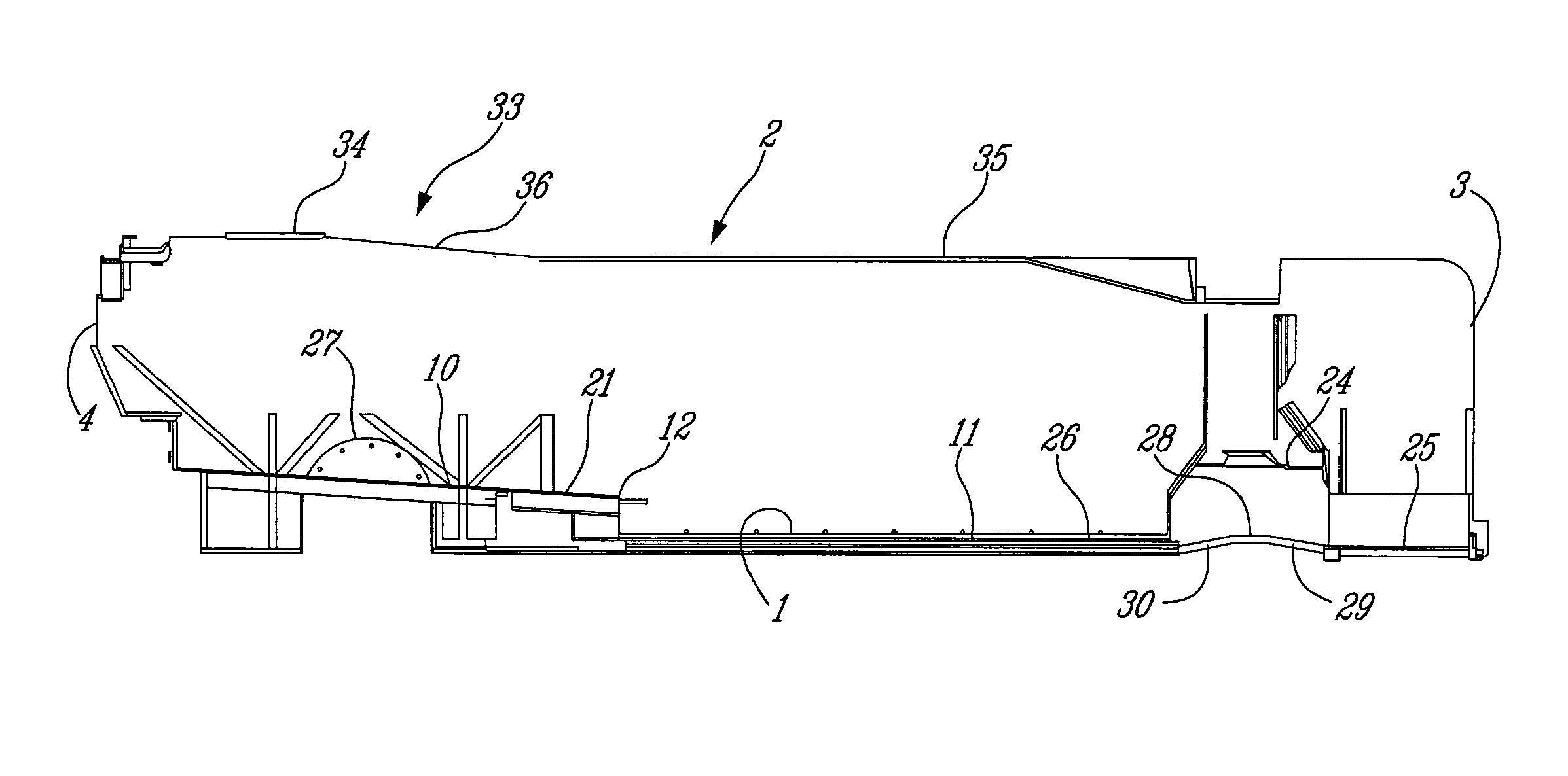
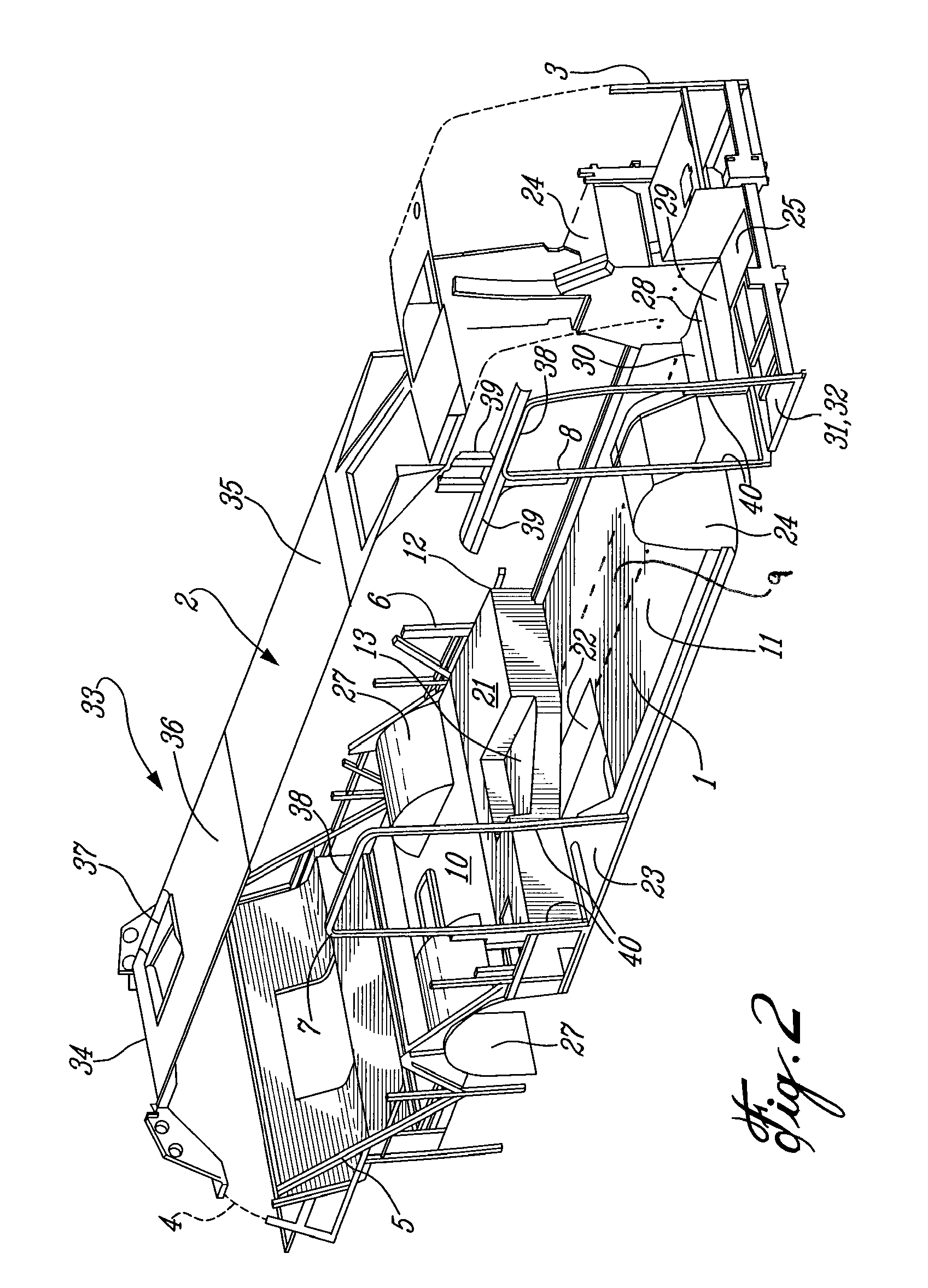
[0009]Among other advantages, the transition floor module provides increased space for bus equipment under the driverside portion which extends forwardly relative to the curbside portion. The angled aisle or step portion also increases the area of the step which improves the footing of passengers climbing or descending on steps in a moving vehicle, and also increases space for equipment underneath. The increased space provided beneath the transition module causes an equal reduction in space within the passenger cabin; however, since seats can be mounted on the upper driverside surface of the transition module, only under-seat space is reduced. This space is not normally utilized in transit buses.
[0010]Further, the angled front wall of the transition floor section provides an angled bumper to more easily redirect wheeled devices laterally after colliding axially. The angled front wall wheeled redirects devices toward the rear doors and reduces the tendency for wheeled devices to become trapped in a right angle corner after collision with the step. The reduced difficulty in exiting through the rear doors, will encourage one-way flow of all passengers from front to rear and therefore will improve the overall efficiency of all passenger movements through the bus.

Problems solved by technology

The upper floor section is generally not accessible to wheelchairs or other wheeled devices.
Due to the lower forward floor design, space for engine machinery, fuel tanks, and other bulky equipment within the bus is generally limited to beneath the rear upper floor.
However, such available space may be inadequate for certain bus configurations.
Wheelchairs, baby carriages and other wheeled devices may collide or otherwise interfere with the step and become difficult to redirect laterally out the rear doors.
Typically, wheelchair passengers and those with wheeled devices such as baby carriages prefer to exit through the front doors due to difficulty in navigating out the rear doors.
This impedes entry of passengers through the front doors and generally slows down transit service as a result.

Method used


Image

  • Bus cabin structure
  • Bus cabin structure
  • Bus cabin structure

Examples


Embodiment Construction

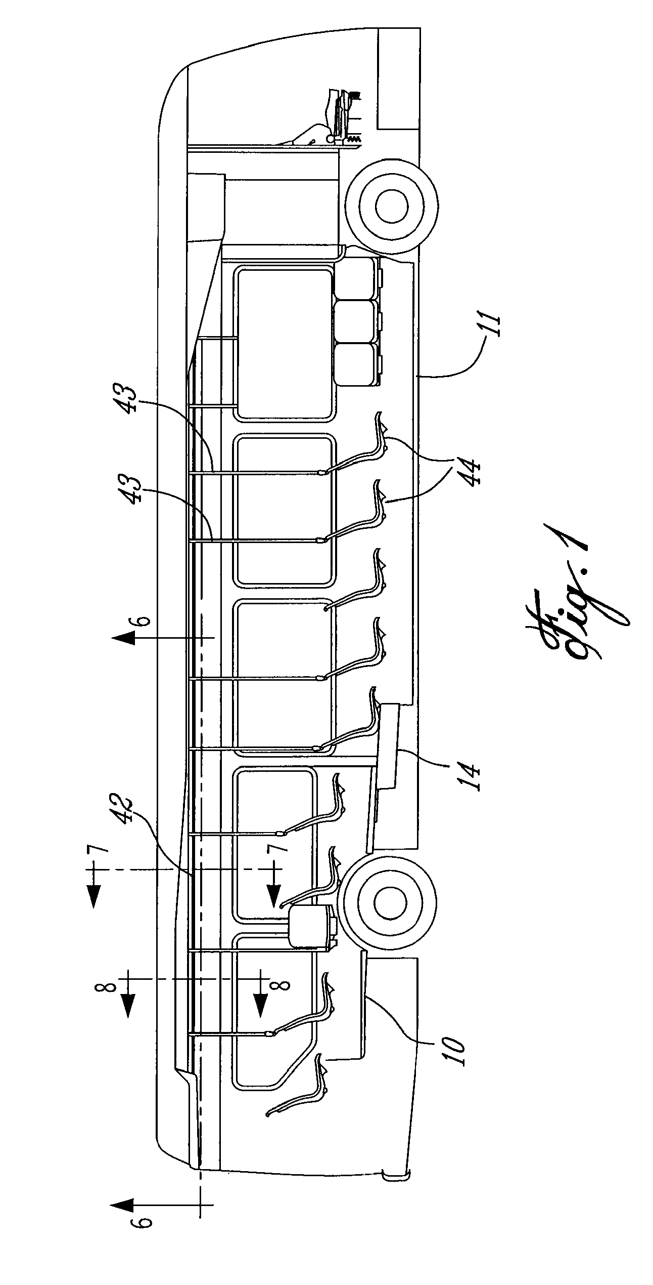
[0025]FIG. 1 shows a longitudinal sectional view of a passenger bus to illustrate the layout of the interior passenger cabin, many parts of which are commonly used and known to those skilled in the art, so only a brief description is necessary. The bus is made wheel chair accessible by having a lower front floor 11 and lower thresholds for passenger exit and entrance doors (see door locations 7, 8 in FIG. 2), with optionally axle suspension that may be actuated up and down to kneel or tilt as close as possible to the road or curb level, such as 14 inches or less. The front wheel wells protrude into the cabin and a central aisle permits passage from the front door towards the rear door. The rear portion of the floor 10 is raised to accommodate the rear axle, transmission and house other equipment. The rear portion of the floor 10 is accessible via one or more steps 14 and so is not wheel chair accessible. Seats 44 are supported with vertical stanchions 43 mounted to a longitudinal ra...


PUM


Abstract

Bus cabin structures including improved configurations of floors, passenger aisles and steps, interior roofs or ceilings, and door frames.

Description

TECHNICAL FIELD[0001]The invention relates to floor and ceiling structures for transit buses and other vehicles. In particular, the invention relates to bus cabin structures having lower floors and upper floors, with transition floor modules therebetween, the transition modules having central aisles with recessed steps and angled front walls.BACKGROUND OF THE ART[0002]The invention relates to cabin structures for vehicles, such cabins as used in wheelchair-accessible and other transit bus cabins. To allow access by passengers in wheelchairs, and disabled, elderly, or other passengers who have difficulty with stairs, including for example passengers with wheeled baby carriages or wheeled carrying devices, buses are commonly designed with a lower front floor section.[0003]Such floors may be made increasingly accessible when the bus stops by, for example, operating “kneeling” front suspension or lateral tipping suspension mechanisms to bring the floor adjacent the front and rear doors ...

Claims


Application Information

Patent Timeline
Patent Type & Authority Patents(United States)
IPC IPC(8): B62D25/20
CPCB62D31/02B62D47/02
Inventor KERR, ANDREWNAYLOR, GLENCANTIN, PAULCYCHOWSKI, TOMASZEGILSON, KRISTOPHERFAST, JORDAN
Owner NEW FLYER INDS CANADA ULC
Learn More