Surgical instrument with elastically movable instrument head

a surgical instrument and elastic technology, applied in the field of surgical instruments, can solve the problems of insufficient assembly space, inability to completely decouple individual movements, and inconvenient operation, and achieve the effect of more working spa

Active Publication Date: 2014-11-04
TUEBINGEN SCI MEDICAL
View PDF14 Cites 908 Cited by
  • Summary
  • Abstract
  • Description
  • Claims
  • Application Information

AI Technical Summary

Benefits of technology

[0015]Another aspect of the invention is directed to the tube or instrument shaft of the surgical instrument which shaft is formed in a single C-shape along its longitudinal direction or comprises a plurality of single curved portions having identical or different radii to each other to simulate a C-shaped curve (in one plane). This shaft design forms the basis to insert a plurality (at least two) of surgical instruments of the invention into a single trocar in case of a so-called single port surgery wherein the signal generators (handles) of each instrument do not interfere each other. Furthermore, the C-shape or C-shape like form has the advantage in that the distal end portions of the instruments are automatically distanced from each other such that there is no need anymore to cross the instruments shafts when passing through the single port trocar to achieve a specific distance between the distal end portions as is the case in the prior art. Additionally, the instruments can be inserted and removed into/out of the trocar separately and individually from each other.
[0016]It shall be noted here, that the single curve direction of each instrument shaft is in conformity with the pivoting direction of the instrument head. In other words, in case two surgical instruments having (single) curved instruments sha

Problems solved by technology

However, such a transmission is necessarily extremely complex and consequently also requires sufficien

Method used


Image

  • Surgical instrument with elastically movable instrument head
  • Surgical instrument with elastically movable instrument head
  • Surgical instrument with elastically movable instrument head

Examples


Embodiment Construction

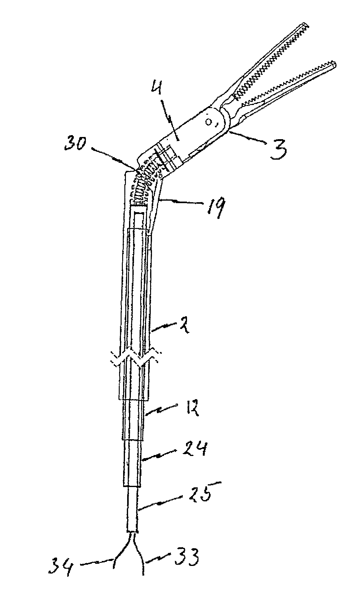
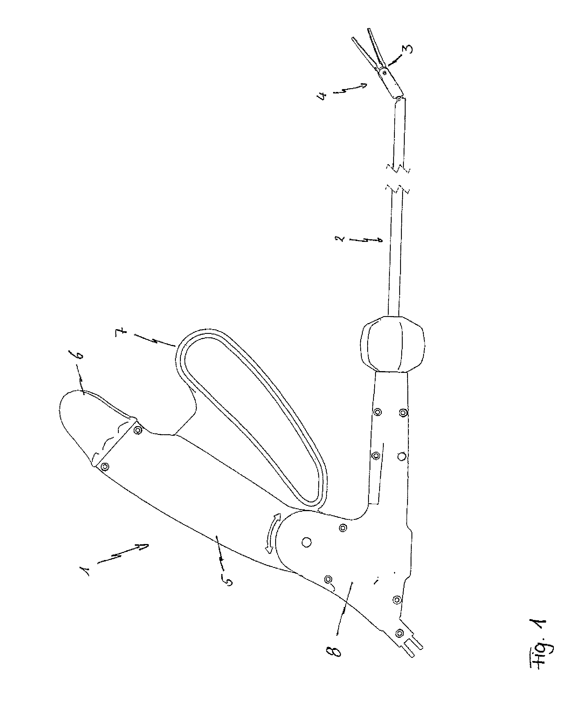
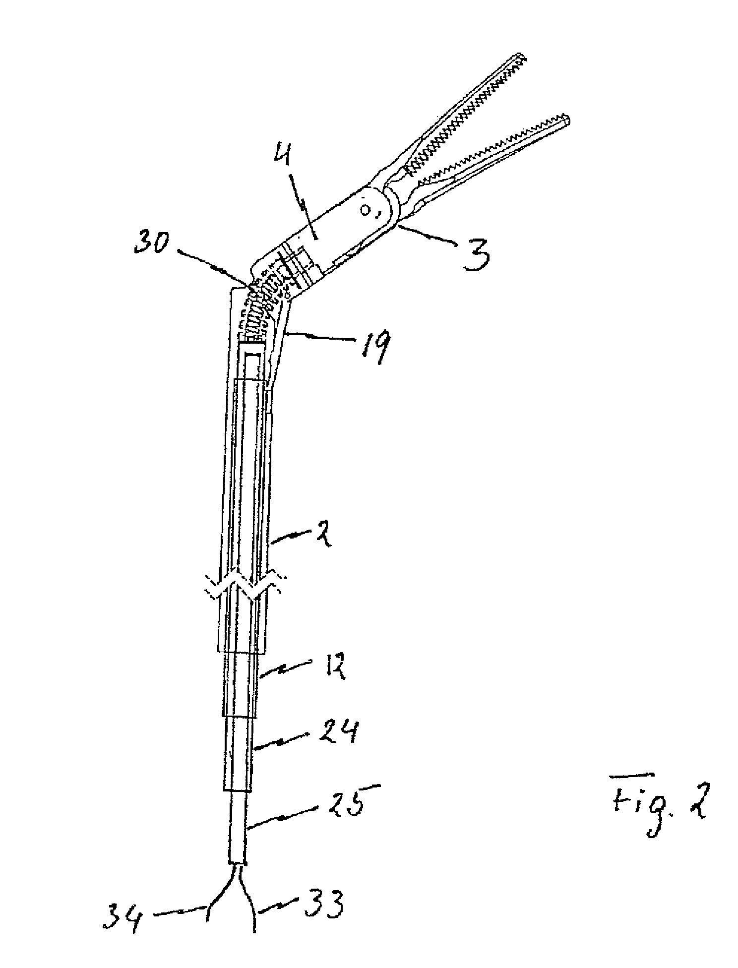
[0024]In FIG. 1, a complete surgical instrument according to a preferred embodiment of the invention is shown in a perspective view. The surgical instrument according to the invention consequently has a mechanical signal generator in the form of a multi-functional instrument handle 1 which is arranged at a proximal end or end portion of a tube or instrument shaft 2, preferably made of stainless steel, as well as an instrument head 4 equipped or adapted to be equipped with an effector 3, the instrument head being provided at the other, distal end of the instrument shaft 2.

[0025]As can be seen from FIG. 1 the tube or instrument shaft 2 can have a C-shaped curve wherein the C-shape is achieved by a single radius or by a plurality of curved portions (having the same curving direction) distanced from each other in the longitudinal direction and having identical or different radii, respectively. Alternatively, the instrument shaft 2 can also have a straight shape or the instrument shaft h...


PUM


Abstract

Disclosed is a surgical instrument comprising an instrument handle, an instrument shaft shaft having a distal end and a proximal end at which the instrument handle is linked, an instrument head, pivotally linked to the distal end of the instrument shaft via a hinge shaft or pins and comprising an effector rotatably supported in said instrument head around its longitudinal axis as well as a surgical tool held by said effector, and a mechanical transmission system at least partially arranged within said instrument shaft transmitting mechanical operation signals from said instrument handle to said instrument head at least for pivoting and/or rotating motions. A bending flexible as well as rotating rigid, hollow spindle is arranged bypassing said hinge shaft or pins and directly connecting said effector with the mechanical transmission system for transmitting at least rotating signals via said spindle to said effector.

Description

BACKGROUND OF THE INVENTION[0001]1. Field of the Invention[0002]The present invention relates to a surgical instrument especially for minimally invasive surgery having a distal instrument head moveably connected to an instrument or tube shaft.[0003]2. Discussion of the Prior Art[0004]For example, from DE 100 36 108, a surgical instrument of this kind is known. It substantially consists of a tube or instrument shaft at the one proximal end of which an instrument handle is arranged for the operation of an instrument head disposed at the opposed distal end of the tube shaft via a transmission path. The instrument head can be bent, or rather inclined with respect to the tube shaft and, moreover, holds an effector rotatably supported in the instrument head in the form of a type of forceps or tongs, one jaw of which is pivotably supported on the effector and is likewise operable by means of the instrument handle.[0005]In more concrete terms, the transmission enables at least a first movem...

Claims


Application Information

Patent Timeline
IPC IPC(8): A61B17/29A61B17/00A61B18/14
CPCA61B2017/291A61B18/1445A61B2017/2902A61B2017/2929A61B2017/294A61B2017/00738A61B17/29A61B2017/2906A61B2017/2927
Inventor BRAUN, MARCUS
Owner TUEBINGEN SCI MEDICAL
Why Eureka
Try Eureka