Dialyzer with dual safety valves

a safety valve and dialyzer technology, applied in the field of hemodialysis apparatus, system and/or method, can solve the problems of waste products, inability to provide suitable means to close off the inlet and outlet, etc., and achieve the effects of ensuring the well being of the caregiver and patient, convenient and easy use, and durable design

Inactive Publication Date: 2014-11-04
LOVELL GLORIA
View PDF24 Cites 4 Cited by
  • Summary
  • Abstract
  • Description
  • Claims
  • Application Information

AI Technical Summary

Benefits of technology

[0003]Given the above deficiencies of prior art, a need remains for a dialyzer with novel assembly to shield the caregiver and patient from dialysis hazards. The present invention satisfies such a need by providing an assembly that is convenient and easy to use, is durable in design, and ensures the well being of the caregiver and patient by greatly reducing incidences of exposure to germs, bacteria and blood-borne pathogens so often associated with administering dialysis treatment. The assembly is not only limited to protecting the caregiver from exposure to harmful bio-hazardous waste, by preventing the dialyzer from spilling or leaking fluids, but use of the present invention also ensures that hospital flooring remains clean and dry during the dialysis procedure. As such, caregivers and patients alike are spared the dangers of slipping and falling which can easily occur when traversing a slippery floor.
[0006]Preferably, the apparatus further includes a third check valve disposed between the fluid inlet and a fluid entry line leading to the dialyzer casing; and a fourth check valve disposed between the fluid outlet and a fluid exit line departing from the dialyzer casing. As with the first and second check valves, the third and fourth check valves also restrict flow in only one direction.

Problems solved by technology

The problem is that there are no suitable means available to close off the inlet and outlet of the dialyzer, thus exposing the patient and caregiver to waste products as they remove the dialyzer from the dialysis machine.

Method used


Image

  • Dialyzer with dual safety valves
  • Dialyzer with dual safety valves
  • Dialyzer with dual safety valves

Examples


Embodiment Construction

)

[0011]The present invention will now be described more fully hereinafter with reference to the accompanying drawings, in which a preferred embodiment of the invention is shown. This invention may, however, be embodied in many different forms and should not be construed as limited to the embodiment set forth herein. Rather, this embodiment is provided so that this application will be thorough and complete, and will fully convey the true scope of the invention to those skilled in the art.

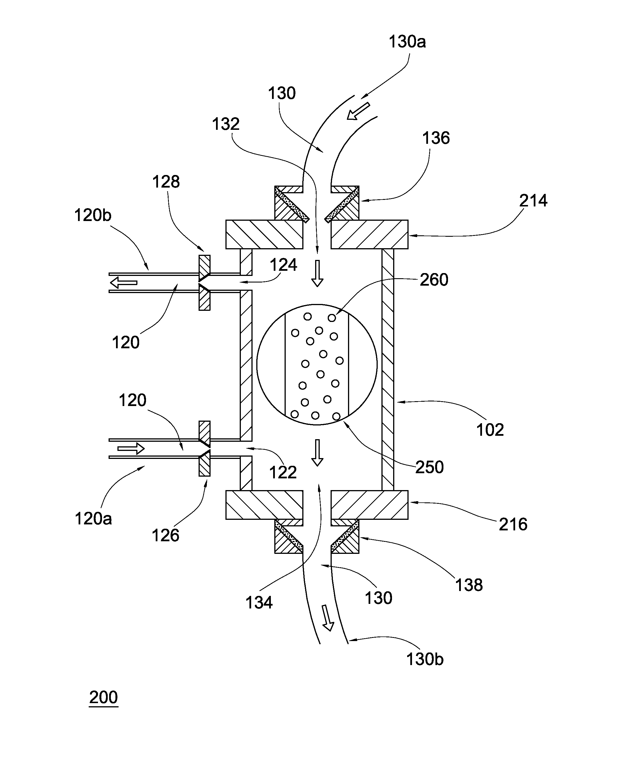
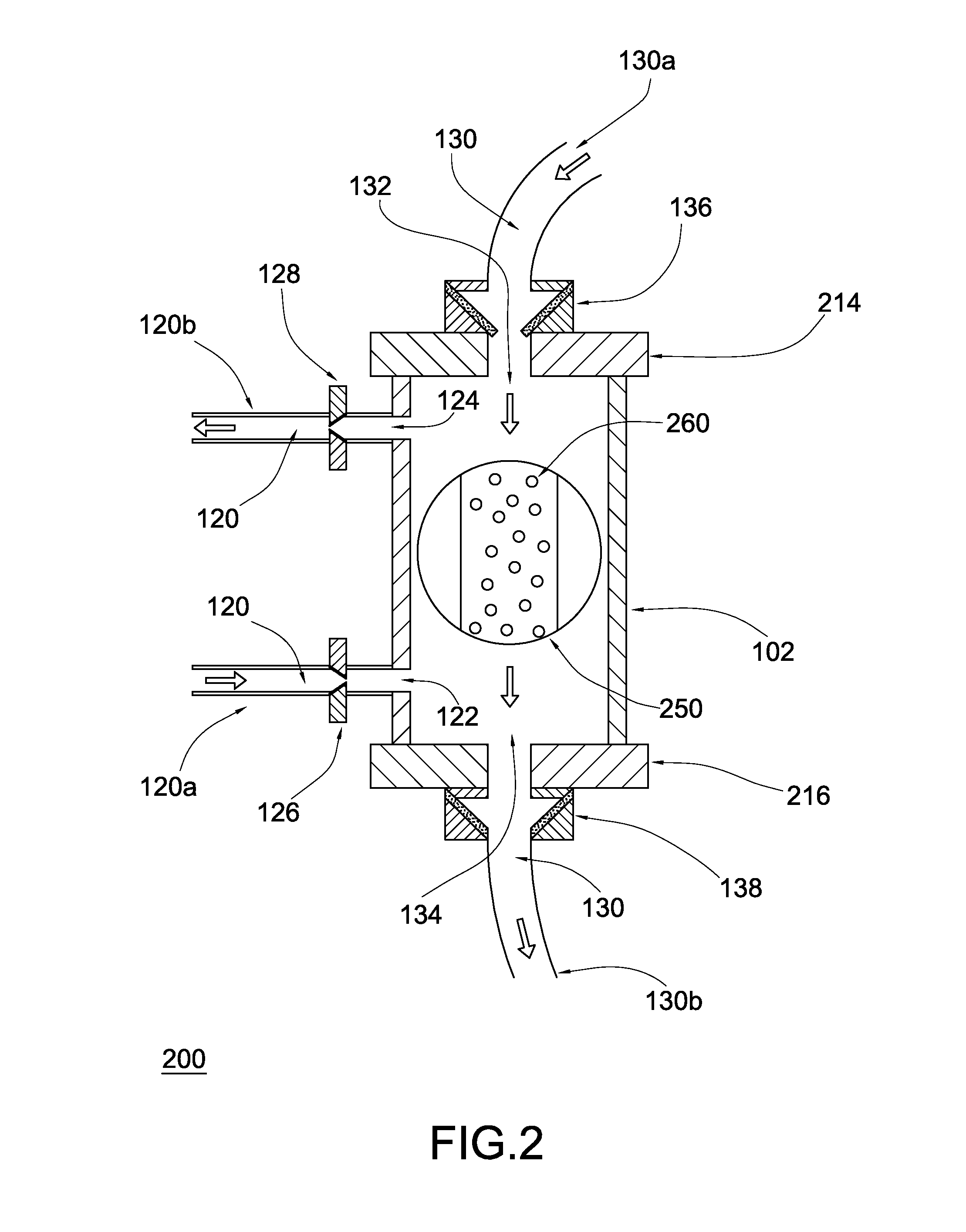
[0012]The assembly of this invention is referred to generally in the figures and is intended to provide a dialyzer with dual safety valves. It should be understood that the assembly may be used to provide dual valve filters in many different types of applications and should not be limited in use to only dialysis.

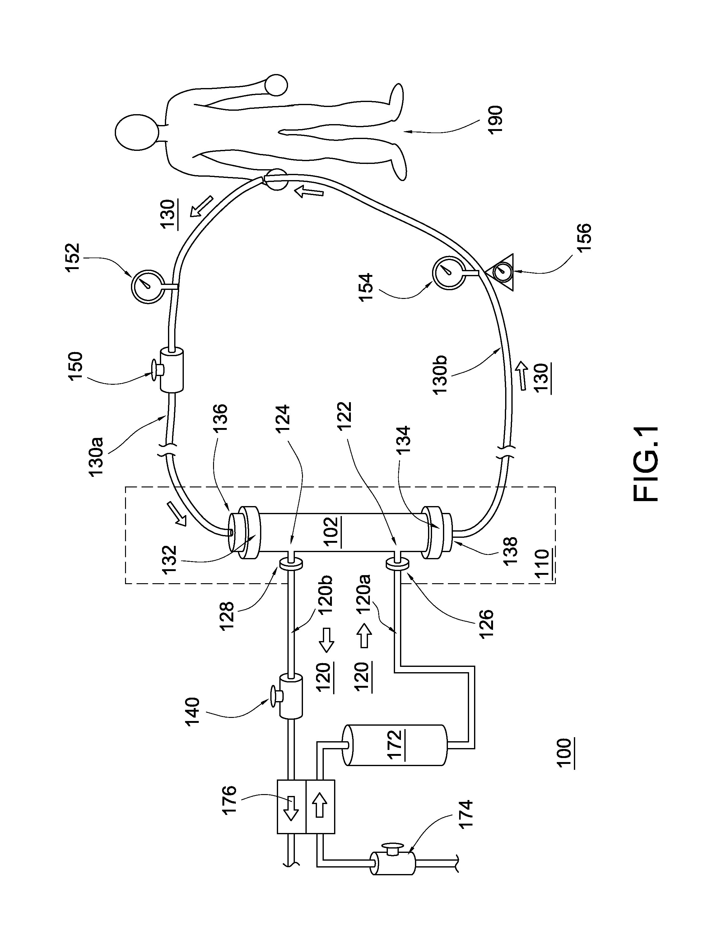
[0013]FIG. 1 depicts a hemodialysis apparatus 100 with a dialyzer assembly 110 embodying the present invention therein. The dialyzer assembly 110 includes a casing 102 that is suitably sized ...


PUM

PropertyMeasurementUnit
semi-permeableaaaaaaaaaa
mass transferaaaaaaaaaa
pore sizesaaaaaaaaaa

Abstract

An apparatus for purifying body fluid with solution including a casing having first and second input and output ports and dual safety or check valves monolithically formed with the casing that operate in conjunction with a dialysis machine or other apparatus used in hemodialysis is disclosed. The dual safety valves are configured at the input and output ports of a dialyzer such that the apparatus allows body fluid to move in one direction. This configuration prevents the reverse flow of body fluid back into the apparatus. A method for purifying body fluid with solution using an apparatus is further disclosed.

Description

BACKGROUND OF THE INVENTION[0001]This invention relates to an apparatus, system and / or method for hemodialysis and, more particularly, to a dialyzer with dual safety valves for stopping dialysis solution from reversing and leaking through input and output ports.[0002]Artificial kidney systems usually include a dialyzer and a dialysis machine which controls the operation of the dialyzer. The dialyzer is used to treat a patient's blood so as to remove water and waste products therefrom. Such dialyzers include a semi-permeable membrane which separates the blood and the dialysis solution flowing through the dialyzer. Waste product removal occurs by mass transfer through the membrane, and water removal occurs by ultrafiltration through the membrane. When a dialysis session is finished, it is necessary to remove the dialyzer and discard thereof. The problem is that there are no suitable means available to close off the inlet and outlet of the dialyzer, thus exposing the patient and caregi...

Claims


Application Information

Patent Timeline
Patent Type & Authority Patents(United States)
IPC IPC(8): B01D61/00B01D21/24B01D63/00A61M1/16B01D11/00
CPCA61M1/16A61M1/1621
Inventor LOVELL, GLORIA
Owner LOVELL GLORIA
Why Eureka
Try Eureka