Device and method for generating a drop of a liquid

a technology of liquid drop and device, which is applied in the direction of positive displacement liquid engine, laboratory glassware, instruments, etc., can solve the problems of high risk of damage, increased risk, and no longer feasible operation of the same with highly viscous media

Active Publication Date: 2014-11-04
ALBERT LUDWIGS UNIV FREIBURG
View PDF13 Cites 5 Cited by
  • Summary
  • Abstract
  • Description
  • Claims
  • Application Information

AI Technical Summary

Benefits of technology

[0035]Hence, embodiments of the present invention also provide a device and a method for generating liquid drops by two-phase flow. Thereby, the embodiments allow dosing of drops of a liquid primary fluid or drops of a primary liquid by ejection from a nozzle or a channel. Further, embodiments are implemented to cause the drop tear-off or the drop generation already within the nozzle or within the channel by a fluid flow of a secondary fluid or drive fluid at least partly surrounding the primary liquid.

Problems solved by technology

The needles are constantly at a high risk of being damaged.
This risk is even increased when dosing has to be performed in areas that are not topographically even.
Hence, this is also the disadvantage of the method.
The jet disintegration depends heavily on the viscosity, such that the same no longer functions in a feasible manner with highly viscous media.
On the one hand, the surface tension draws the drop back, but results, on the other hand, in instability of the resulting constriction as in jet decomposition, which can result in a pinch-off of single drops.
Another disadvantage is that the pinch-off of the drop becomes slower with increasing viscosity, and the functionality with respect to drops that are as small as possible is limited by the nozzle radius.
It is a disadvantage of this method that no single drops can be dosed therewith, and the feature sizes are too small, for example for metallic mold making.
Corresponding to the above described open-jet disintegration, this interface is energetically unstable and generation of single drops of the inner medium is forced.
However, conventional examples of this application are not known.

Method used


Image

  • Device and method for generating a drop of a liquid
  • Device and method for generating a drop of a liquid
  • Device and method for generating a drop of a liquid

Examples


Embodiment Construction

[0054]In the figures, the same reference numbers are used for the same or for equal or similar features or functional units.

[0055]For the term primary liquid, the terms primary fluid, primary phase or primary medium are used as well, and for the term secondary fluid, the terms secondary medium or drive fluid or, depending on the embodiments, also secondary gas are used as well.

[0056]Embodiments of the device for generating a drop can thereby be used as dosing apparatus or dosing device, for example for non-contact dosage of liquids. Wherein liquids can, for example, also be melted polymers or metals.

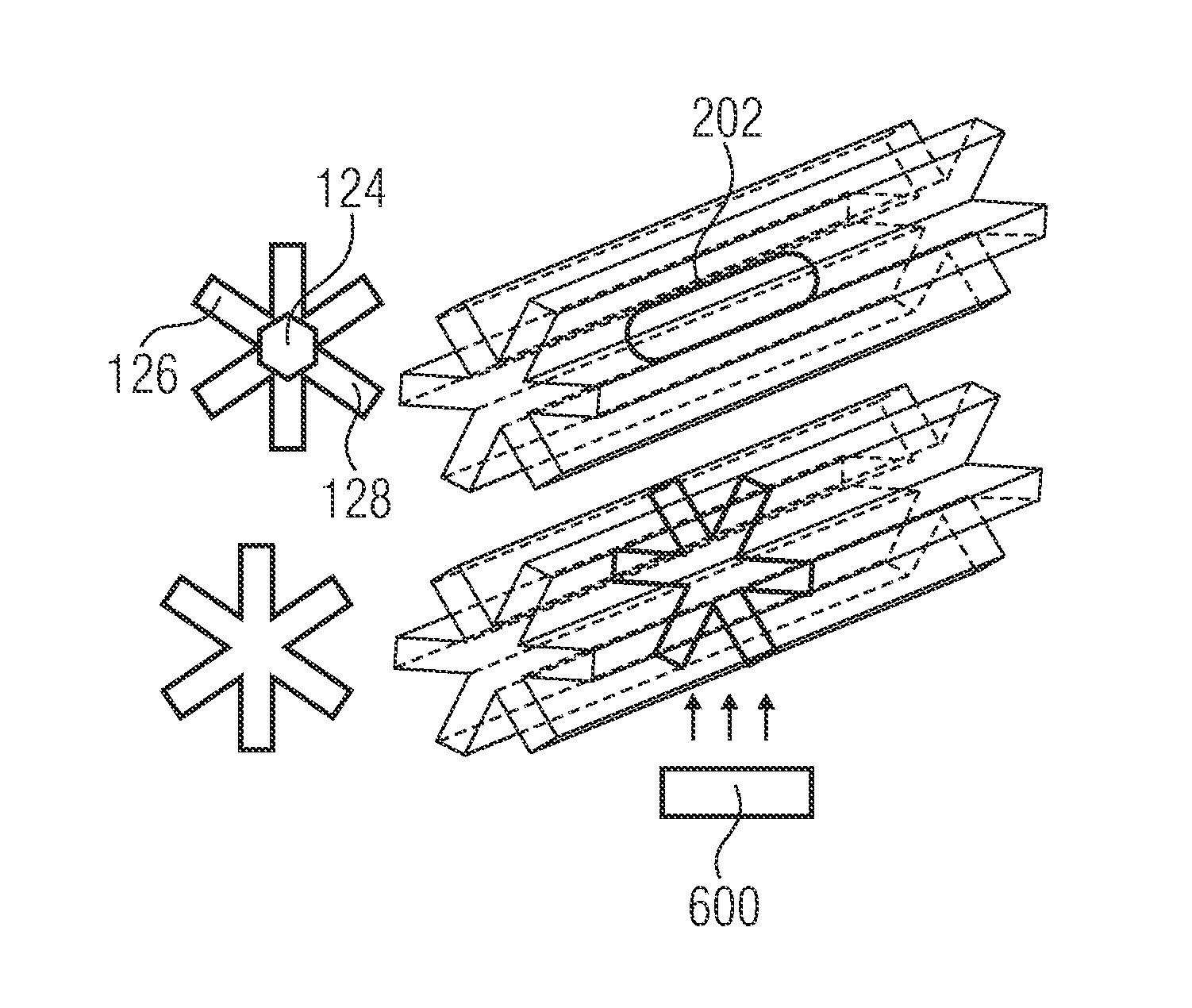
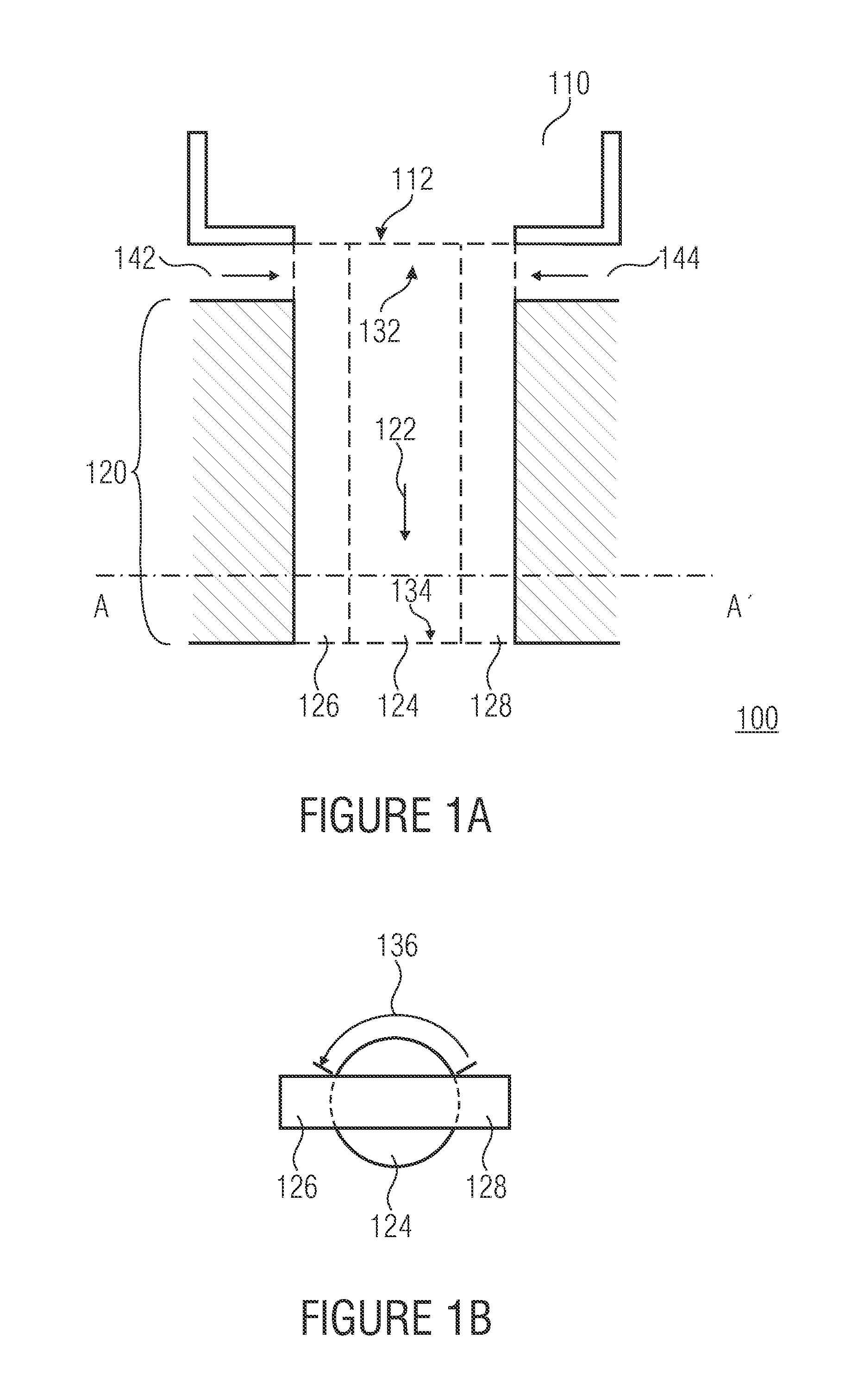
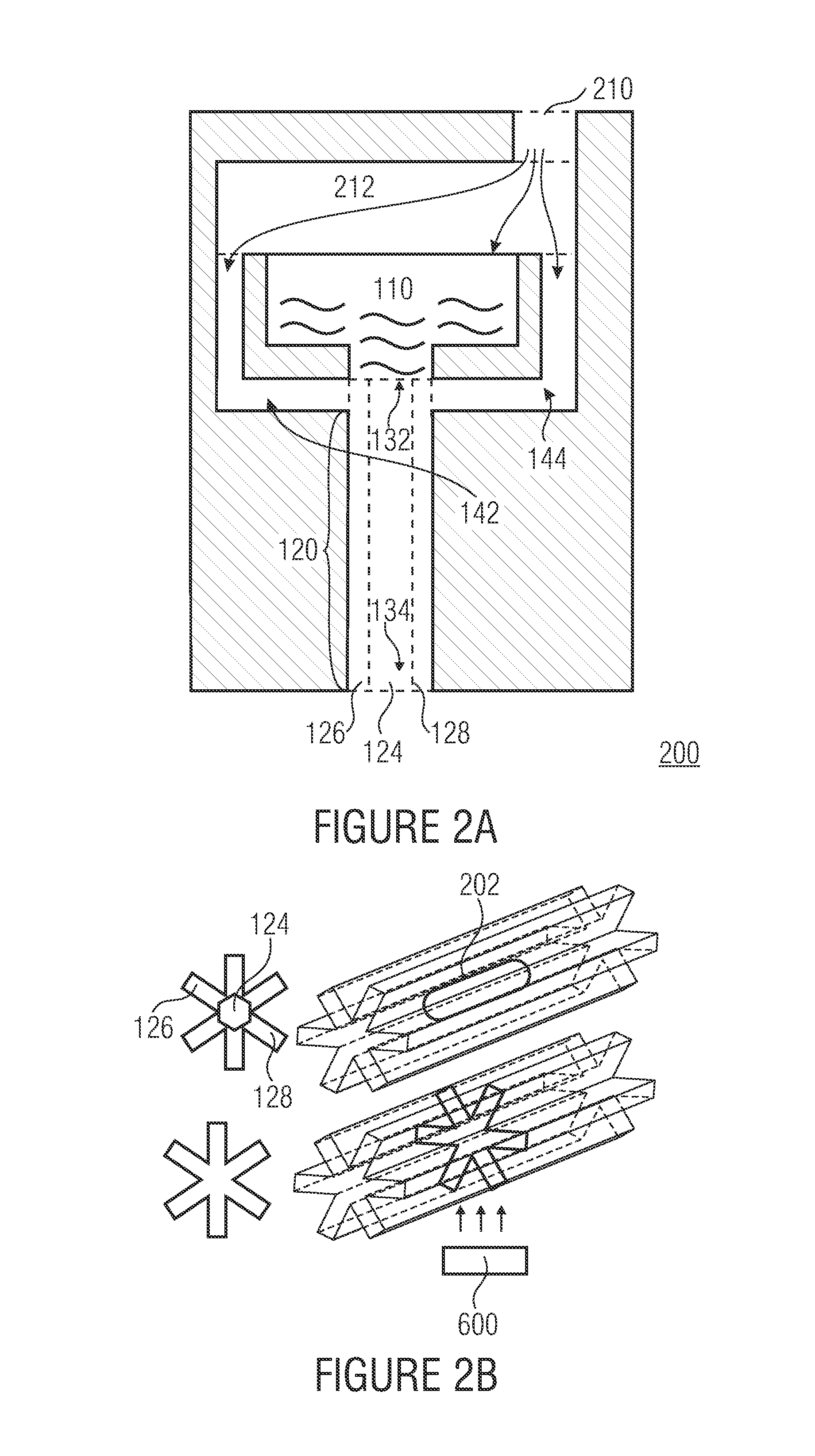
[0057]FIG. 1A shows a schematic longitudinal section of an embodiment of a device 100 for generating a drop of a primary liquid having a reservoir 110 and a channel 120. FIG. 1B shows a schematic cross-section A-A′ of the device 100 according to FIG. 1A or a flow cross-section transverse to a main flow direction (see arrow with reference number 122) of a secondary fluid, wherein the flow...


PUM

PropertyMeasurementUnit
angleaaaaaaaaaa
angleaaaaaaaaaa
contact angleaaaaaaaaaa

Abstract

A device for generating a drop of a primary liquid is described, including: a reservoir fillable with the primary liquid, a pressure generation device for generating a hydraulic pressure on the primary liquid, at least one inlet channel for introducing a secondary fluid, and a channel having a flow cross-section transverse to a main flow direction, wherein the flow cross-section includes a main region and at least one sub-region extending from the main region, designed such that the primary liquid can be held in the main region by capillary forces, and the secondary fluid can be held in the sub-region by capillary forces, wherein the reservoir is fluidically connected to a first end of the channel via an output opening, and the at least one inlet channel is also fluidically connected to the channel, and wherein the pressure generation device is implemented to apply a hydraulic pressure to the primary liquid, whereby the same is moved along the channel and output at a second end of the channel as free-flying drop.

Description

CROSS-REFERENCE TO RELATED APPLICATIONS[0001]This application is a continuation of International Application No. PCT / EP2009 / 008097, filed Nov. 13, 2009, which is incorporated herein by reference in its entirety, and additionally claims priority from German Application No. DE 102008057291.8, filed Nov. 14, 2008, which is incorporated herein by reference in its entirety.BACKGROUND OF THE INVENTION[0002]The present invention relates to devices and methods for generating a drop of a liquid, e.g. for dosing systems for the dosage of small amounts of liquids.[0003]The dosage of small amounts of liquids is widespread in many fields of application from inkjet printer to the production of microarrays, and different methods are used. Such methods are described, for example, in the following expert publications: P. Koltay, G. Birkle, R. Steger, H. Kuhn, M. Mayer, H. Sandmaier and R. Zengerle, “Highly Parallel and Accurate Nanoliter Dispenser for the High-Throughput-Synthesis of Chemical Compou...

Claims


Application Information

Patent Timeline
Patent Type & Authority Patents(United States)
IPC IPC(8): B41J2/21B01L3/02B22D41/05B22D41/005
CPCB41J2/211
Inventor METZ, TOBIASKOLTAY, PETER
Owner ALBERT LUDWIGS UNIV FREIBURG
Why Eureka
Try Eureka