Encoder with gear mechanism and optical encoder device

a gear mechanism and encoder technology, applied in the field of encoders, can solve problems such as error detection

Inactive Publication Date: 2014-11-04
SANYO DENKI CO LTD
View PDF32 Cites 3 Cited by
  • Summary
  • Abstract
  • Description
  • Claims
  • Application Information

AI Technical Summary

Benefits of technology

[0006]An object of the present invention is to provide an encoder including a position detecting device provided with a gear mechanism and an optical encoder device, in which constituent parts of the optical encoder device can be prevented from suffering contamination due to the presence of the gear mechanism.
[0007]The present invention is directed to an encoder including a position detecting device provided with a gear mechanism, an optical encoder device, and a housing that houses the position detecting device and the optical encoder device. In the present invention, the housing is configured to separate the gear mechanism from the optical encoder device. If the gear mechanism is thus separated from the optical encoder device, abrasion powder or grease can be reliably prevented from scattering from the gear mechanism to adhere to constituent parts of the optical encoder device. Therefore, the present invention can provide an encoder including an optical encoder device and a position detecting device including a gear mechanism, in which contamination of constituent parts of the optical encoder device can be prevented, thereby eliminating erroneous detection.
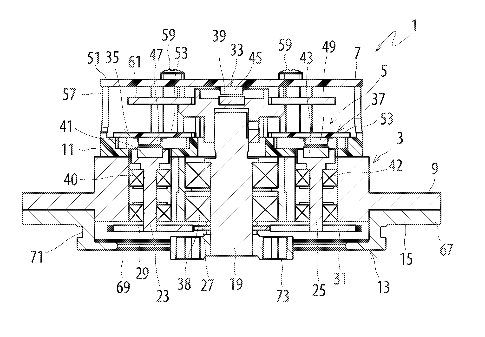
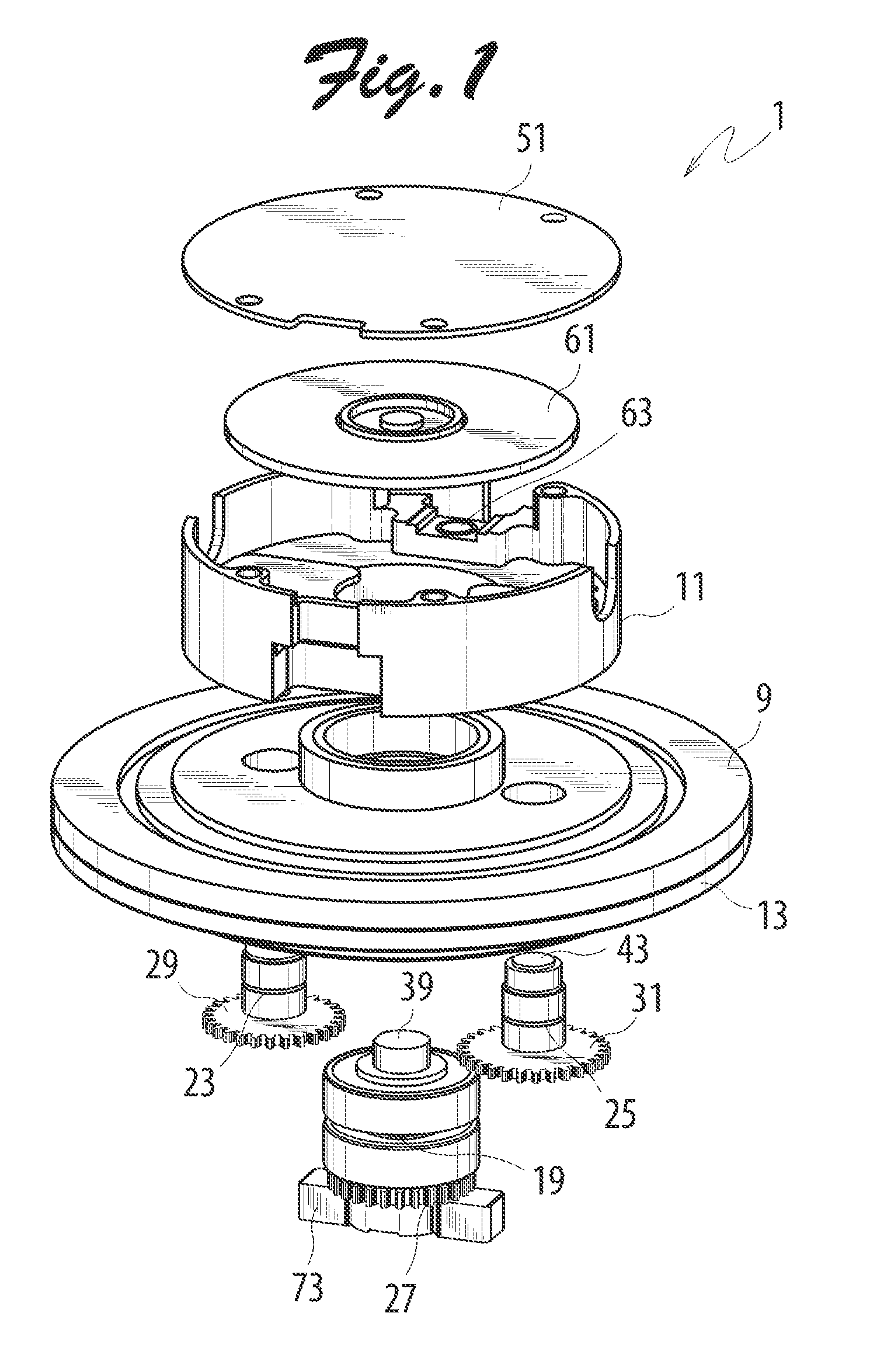
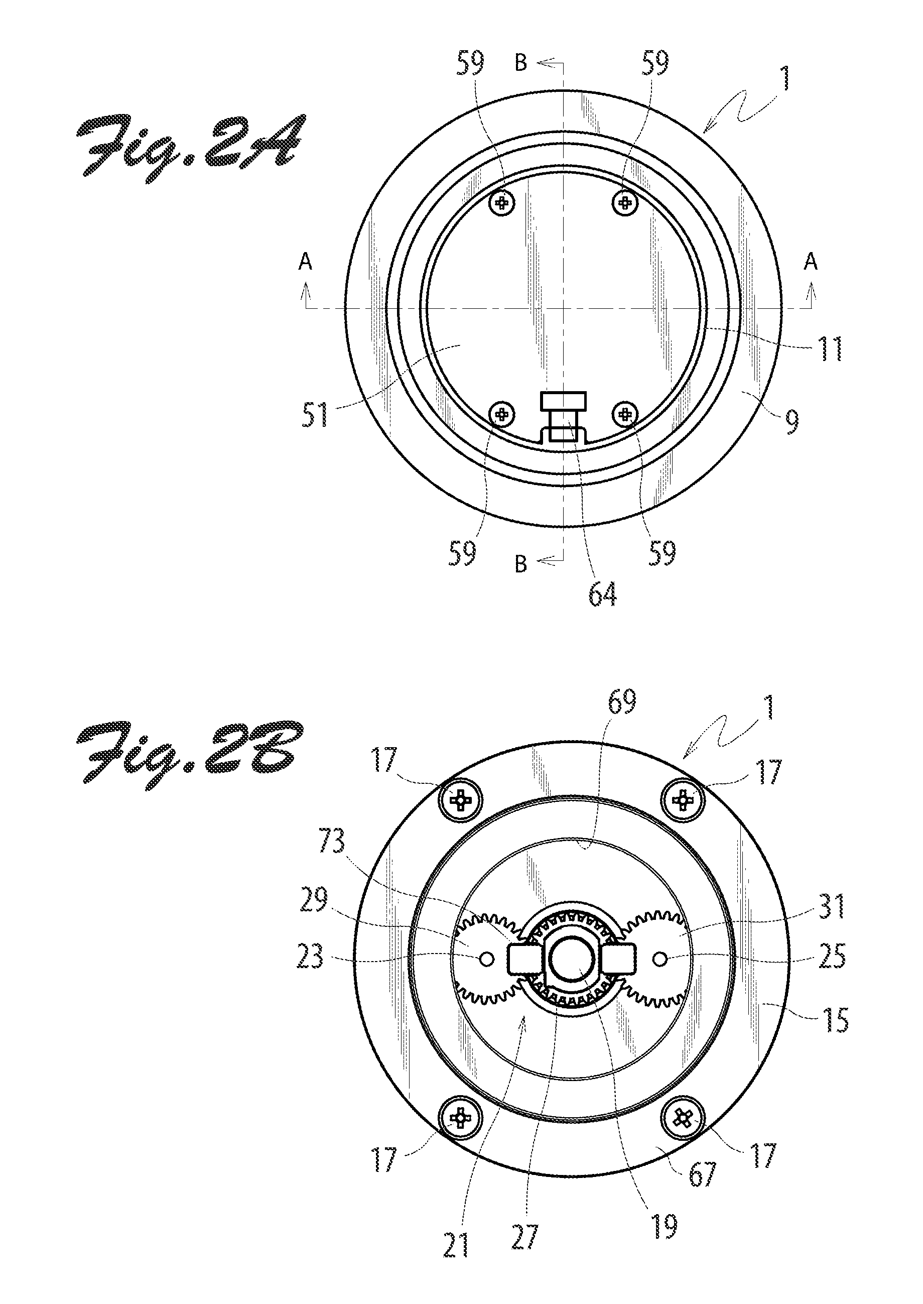
[0011]Specifically, the housing may include a partition wall portion provided with a plurality of bearings capable of rotatably supporting the main shaft and the n sub shafts, a first housing portion configured to house the (1+n) position detecting sections and the optical encoder device, and a second housing portion configured to house the gear mechanism. The partition wall portion may separate the gear mechanism from the (1+n) position detecting sections, the optical encoder device, and the circuit substrate. By using the partition wall portion, the gear mechanism can be reliably separated or isolated with a simple structure.
[0013]The first housing portion of the housing may include a bottom wall portion that contacts the partition wall portion, and a peripheral wall portion integrally provided with the bottom wall portion to extend in a direction away from the partition wall portion. In this configuration, the circuit substrate may be fixed to the peripheral wall portion. This allows the circuit substrate to be utilized as a lid member for the first housing portion, and to be firmly fixed to the first housing portion. Further in this configuration, the first magnetism detecting element may be fixed to the circuit substrate, and a sub circuit substrate may be provided in the first housing portion such that the second to n-th magnetism detecting elements are fixed to the sub circuit substrate. If the second to n-th magnetism detecting elements are disposed on the sub circuit substrate, there may be a space for placement of a rotary disc between the circuit substrate and the sub circuit substrate. Thus, the optical encoder device may include a rotary disc fixed to the main shaft, and a light emitting element and a light receiving element fixed to the circuit substrate. Then, the rotary disc may be disposed between the circuit substrate and the sub circuit substrate. In this configuration, one of the light emitting element and the light receiving element may be fixed to the circuit substrate, and the other may be fixed in the first housing portion. The circuit substrate and the sub circuit substrate may be electrically connected to each other via an electrical connection member to perform position detecting operation without difficulty.
[0014]The second housing portion may include a base member and the partition wall portion, the base member including an annular flange portion fixed to the partition wall portion, and a cylindrical portion integrally provided with the annular flange portion to surround the gear mechanism and having an opening portion formed in the center of the cylindrical portion to expose the first end of the main shaft. If the second housing portion is formed by the base member and the partition wall portion, the gear mechanism can be assembled with the base member removed, thereby facilitates assembling.

Problems solved by technology

However, if the gear mechanism and other constituent parts are housed in the same housing chamber of a housing as is disclosed in JP09-218055A, the rotary disc or other parts used by the optical encoder device may be contaminated with abrasion powder produced by friction between gears or grease applied to reduce wear of the gears, which may trigger erroneous detection.

Method used


Image

  • Encoder with gear mechanism and optical encoder device
  • Encoder with gear mechanism and optical encoder device
  • Encoder with gear mechanism and optical encoder device

Examples


Embodiment Construction

[0021]An absolute encoder according to an embodiment of the present invention will be described in detail below with reference to the drawings. FIG. 1 is an exploded perspective view of an absolute encoder 1 according to the embodiment. In FIG. 1, only main parts are shown, and some parts are not shown. FIGS. 2A and 2B are a plan view and a bottom view, respectively, of the absolute encoder 1 according to the embodiment. FIG. 3 is a cross-sectional view taken along line A-A of FIG. 2A. FIG. 4 is a cross-sectional view taken along line B-B of FIG. 2A. The absolute encoder 1 according to the embodiment is configured such that a magnetic encoder device 5 serving as a position detecting device and an optical encoder device 7 are housed in a housing 3. The housing 3 includes a bearing holder 9 forming a partition wall portion of the housing 3, a first housing portion 11 fixed to the bearing holder 9, and a base member 15 fixed to the bearing holder 9 to form a second housing portion 13 t...


PUM


Abstract

Provided herein is an encoder including a position detecting device provided with a gear mechanism and an optical encoder device. A housing includes a bearing holder provided between a first housing portion and a second housing portion of the housing. The bearing holder serves as a partition wall portion configured to separate the gear mechanism from the optical encoder device. If the gear mechanism is separated from the optical encoder device, abrasion powder or grease can be reliably prevented from scattering from the gear mechanism to adhere to constituent parts of the optical encoder device.

Description

TECHNICAL FIELD[0001]The present invention relates to an encoder including a position detecting device provided with a gear mechanism and an optical encoder device.BACKGROUND OF THE INVENTION[0002]Japanese Patent Application Publication No. 09-218055 (JP09-218055A) discloses an absolute encoder including a combination of a resolver and a magnetic encoder device including a gear mechanism. A circuit substrate having a signal processing circuit mounted thereon and the gear mechanism of the magnetic encoder device are disposed in the same housing portion of a housing.[0003]Japanese Patent Application Publication No. 08-050033 (JP08-050033A) discloses an absolute encoder including an optical encoder device formed by utilizing a single rotary disc and a magnetic encoder device.[0004]In such absolute encoders as disclosed in JP09-218055A and JP08-050033A, multiple rotations are detected by a position detecting device formed by the magnetic encoder device.[0005]In order to store data on th...

Claims


Application Information

Patent Timeline
Patent Type & Authority Patents(United States)
IPC IPC(8): G01D5/34G01D5/12G01D5/347G01D5/249
CPCG01D5/3473G01D2205/26G01D5/26G01D11/24
Inventor MIYAJIMA, TOORUAYUZAWA, TOSHIAKISHOJI, YOSHIHIRO
Owner SANYO DENKI CO LTD
Why Eureka
Try Eureka