Apparatus for horologe with removable and interchangeable face

a technology of horologe and accessory, applied in the field of horologe, can solve the problems of increasing the possibility of losing or damaging any of these components, and the failure of prior art to achieve the effect of achieving the effect of achieving the effect of achieving the effect of achieving the effect of achieving the effect of achieving the effect of achieving the effect of achieving the effect of achieving the effect of achieving the effect of achieving the effect of achieving the effect of achieving the effect o

Active Publication Date: 2014-11-04
JACOBI JR JAMES J
View PDF10 Cites 30 Cited by
  • Summary
  • Abstract
  • Description
  • Claims
  • Application Information

AI Technical Summary

Benefits of technology

[0005]Having the ability to remove and replace the face is very advantageous, whether from a watch on the wearer's wrist or a clock hanging on a wall. This is particularly true when removing and replacing the face can be done quickly and easily, without concern for losing or damaging components or needing to manufacture quantities of additional precision components equal in number to the sum of all removable faces produced. The prior art has failed to achieve this. The present invention creates inexpensive and practical alternatives for removing and interchanging faces in a simple movement, while all portions of the housing of the horologe remain in communication with the horologe.
[0008]The removable face may be used in place of non-removable faces and dials, which are fixed components of most timepieces. The removable face may be thin and substantially flat, and made of a flexible, resilient material on which graphic imagery can be applied by various techniques, including different methods of printing. The face may have an aperture at its central area which, when inserted into the extendable faceplate drawer, aligns with the central aperture of the extendable faceplate drawer, and is of a size sufficient to permit the shaft to extend therethrough. The face also may have a linear passage extending radially from its central aperture toward the perimeter of a face, which when inserted into the extendable faceplate drawer aligns with the linear passage of the extendable faceplate drawer. Aligning the central apertures and linear passages of the removable face and the extendable faceplate drawer, ensures a set position for the removable face when inserted in the extendable faceplate drawer, which will result in optimal viewing of the removable face through both the transparent crystal and the inner transparent cover of the timepiece when the extendable faceplate drawer is inserted into the faceplate compartment.
[0010]The movable armature ring may be made of a durable material and may be located adjacent and parallel to the mount plate of the housing. The extendable faceplate drawer may include a flexible and resilient clip for engaging and disengaging the armature ring. As the faceplate drawer is inserted into the faceplate compartment, the clip engages the armature ring, allowing both the faceplate drawer and the armature ring to move in unison as the insertion of the faceplate drawer is completed. Having the clip engage the armature ring also ensures that the armature ring will move in unison with the faceplate drawer as the faceplate drawer begins to move out of the faceplate compartment. While the extendable faceplate drawer is able to extend from the segregated faceplate compartment, the movable armature ring is prevented from extending beyond a certain point by the shaft of the timepiece. At the point the armature ring reaches the shaft and the faceplate drawer continues to move out of the faceplate compartment, the clip disengages from the armature ring. Prevented from extending any further by the shaft, the armature ring acts as a counterweight, stabilizing the faceplate drawer and counterbalancing its weight when the faceplate drawer is fully extended from the faceplate compartment.
[0011]The invention may be embodied as a horologe with an analog display comprising: (a) a housing which, along with a substantially flat mount plate, encloses a horological movement; (b) a shaft extending in a substantially perpendicular direction from the plane of the mount plate and being operationally connected to the horological movement; (c) at least one hand attached to the shaft and extending in a direction substantially parallel to the plane of the mount plate; (d) a rim extending around the periphery of the housing, the rim having an extendable rim assembly and a non-extendable rim portion; (e) an inner transparent cover and an outer transparent crystal attached to the non-extendable rim portion above the mount plate and defining an enclosed space, the crystal being disposed above the hand and the inner cover being disposed below the hand, the inner cover is spaced from the mount plate of the housing to define a faceplate compartment; (f) a movable armature ring located in the faceplate compartment; (g) an extendable faceplate drawer, which is able to be received into the faceplate compartment adjacent and substantially parallel to the inner transparent cover, having a central aperture of a sufficient size to permit the shaft to extend therethrough, and having a linear passage extending radially from the central aperture toward a perimeter of the faceplate drawer; (h) the extendable rim assembly comprising the faceplate drawer attached thereto, and two flexible, resilient tabs each coupled to a different end of the extendable rim assembly for engagement with and attachment to the non-extendable rim portion; and (i) a thin, substantially flat removable face, removably received in the extendable faceplate drawer. The face may be made of flexible, resilient material having a central aperture of sufficient size to permit the shaft to extend therethrough, and having a linear passage extending radially from the central aperture toward a perimeter of the face. Aligning the central apertures and linear passages of the removable face and the extendable faceplate drawer, ensures a particular position for the removable face when inserted in the extendable faceplate drawer, which will result in optimal viewing of the removable face through both the transparent crystal and the inner transparent cover of the timepiece when the extendable faceplate drawer is inserted into the faceplate compartment.
[0019]The invention may also be described as a horologe comprising, a horological movement, a housing having a substantially flat mount plate and a rim, the rim extending around the housing, an outer transparent crystal attached to the rim, an inner transparent cover attached to the rim, an extendable drawer, a removable face residing in the drawer, and an extendable rim assembly. The horologe may be embodied, for example, as a watch or a clock. The housing protects the horological movement. A portion of the rim is extendable away from the housing to reveal an opening. The inner transparent cover is positioned between the outer crystal and the mount plate of the housing and positioned apart from the housing to create a space between the inner cover and the mount plate so as to form a faceplate compartment. The extendable drawer is adapted for insertion into, and selectably extendable from, the faceplate compartment. The removable face is thin and made of a flexible, resilient material on which graphic imagery can be applied by various techniques. The extendable rim assembly, comprising the extendable rim portion, is attached to the drawer. The drawer is permitted to be selectively extended from the faceplate compartment, but not detached from the horologe. The face is permitted to be removed from the drawer and / or a different face to be inserted into the drawer.

Problems solved by technology

Not only can disjoining these components from the horologe increase the possibility of losing or damaging any of these components (for example, parts of the removable rim assembly, coupled to the removable faces).
The prior art has failed to achieve this.

Method used


Image

  • Apparatus for horologe with removable and interchangeable face
  • Apparatus for horologe with removable and interchangeable face
  • Apparatus for horologe with removable and interchangeable face

Examples


first embodiment

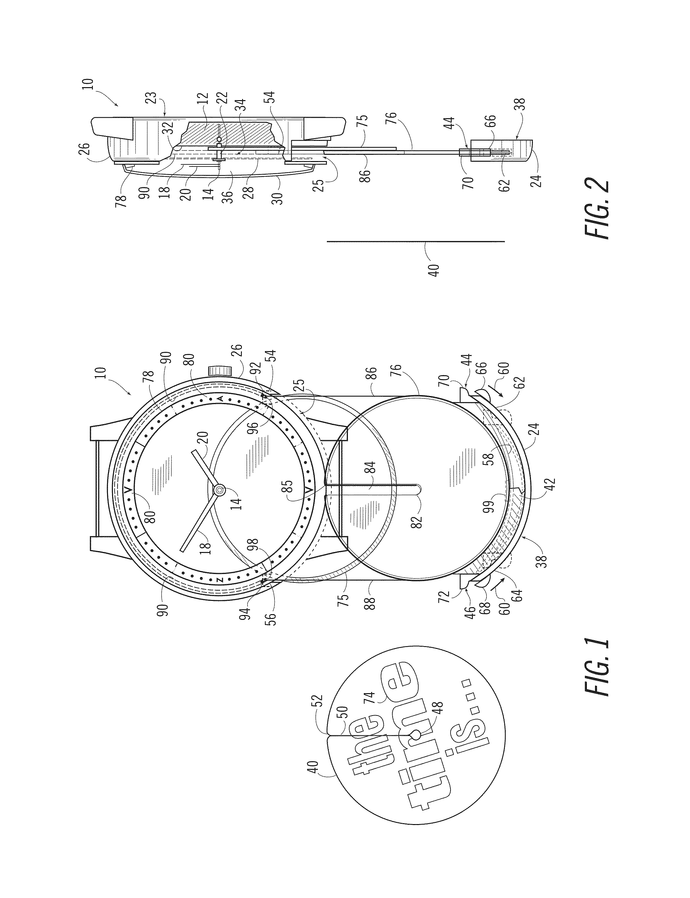
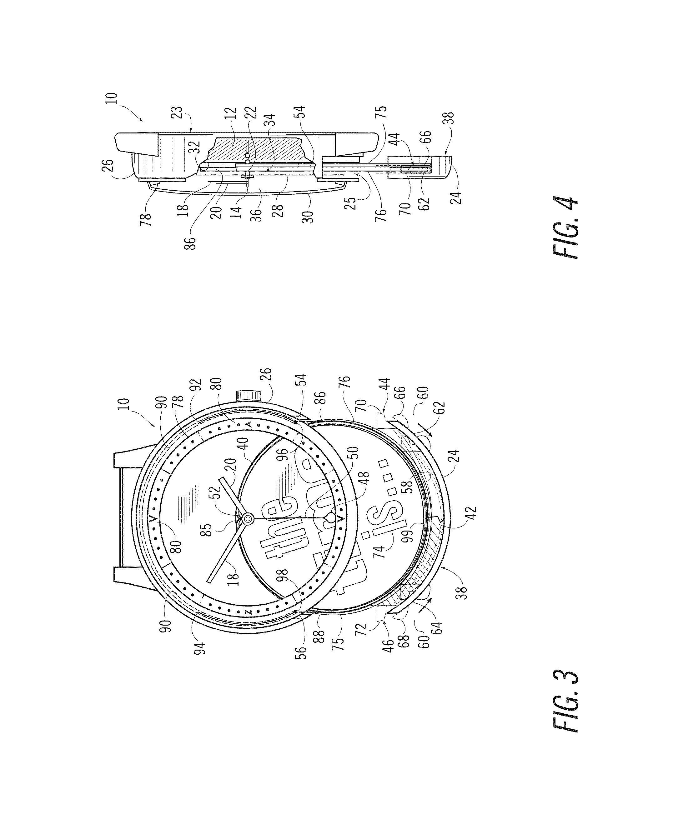
[0057]Referring now to the drawings, wherein like reference numerals refer to like elements, a horologe in accordance with the present invention is shown in FIGS. 1-6 and designated generally by the numeral 10. As shown in FIGS. 2, 4, and 6, horologe 10 comprises a timepiece movement 12, which is encased and sealed. A shaft 14, which drives the minute hand 18 and the hour hand 20, extends out from the movement 12 perpendicular to the plane of the housing 23. Shaft 14 can be encased in an outer protective sleeve 22 if desired. Housing 23 extends around the periphery of movement 12. The horologe 10 may have an extendable rim portion 24 and a non-extendable rim portion 26. An inner transparent cover 28 and an outer transparent crystal 30 may be attached to the non-extendable rim portion 26 creating an outer enclosed space 36, which contains the hands 18 and 20. A segregated faceplate compartment 34 is formed by the space created by the mount plate 32 of housing 23, the non-extendable r...

second embodiment

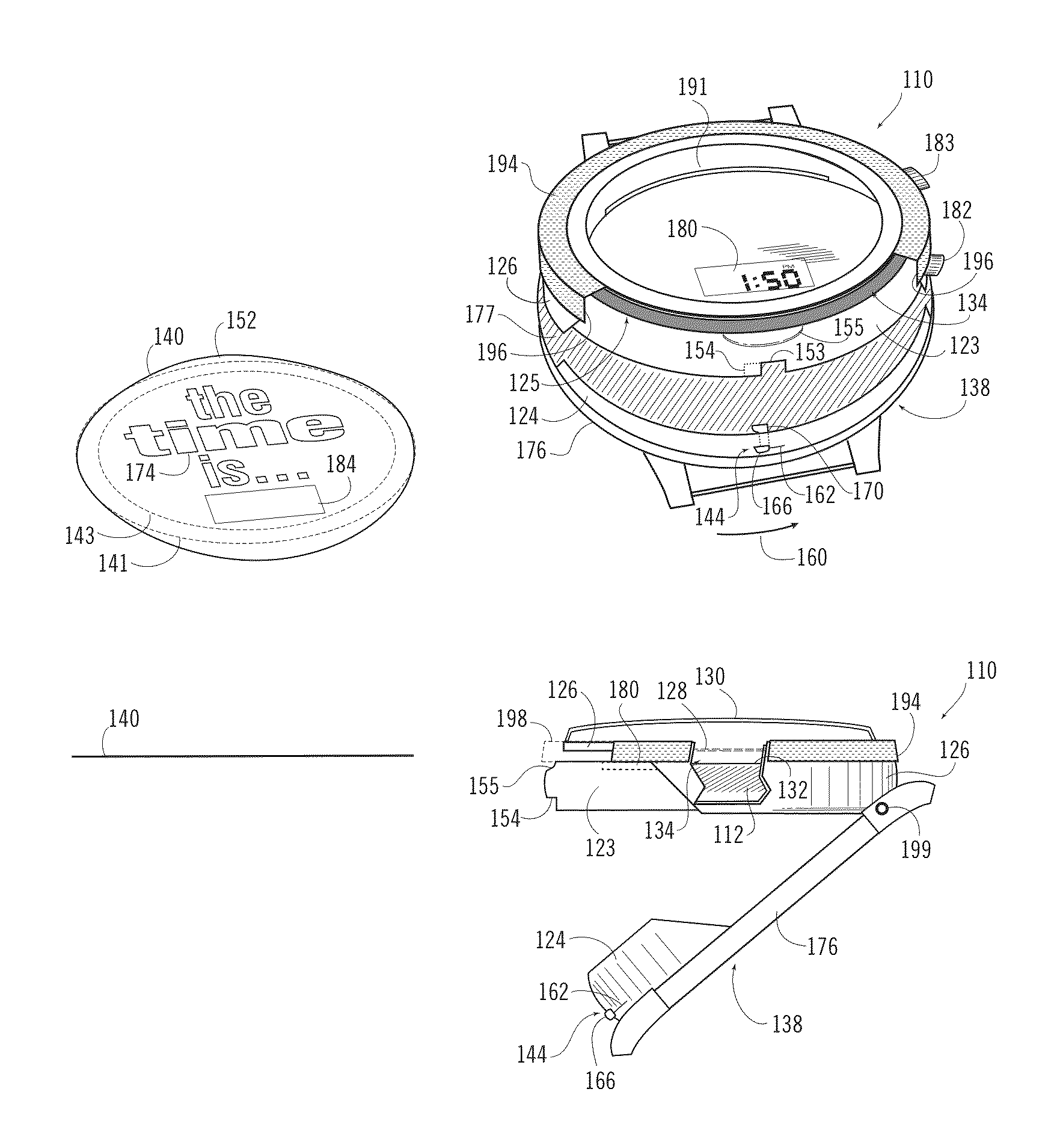
[0073]In the invention, illustrated in FIGS. 7-12, horologe 110 is a watch with a digital display. Some components may be substantially similar to the horologe 10 of the embodiment of FIGS. 1-6, and like elements are identified by the same reference numbers of the 100 series.

[0074]In this embodiment, horologe 110 has a timepiece movement 112 with a digital display 180. In the embodiment illustrated in FIG. 7, digital display 180 is visible through an aperture in mount plate 132. In alternate embodiments, the digital display 180 may be viewed in different locations through a corresponding aperture in mount plate 132. Movement 112 may also include a pair of actuating buttons 182 and 183 for setting the movement 112 in the manner known for conventional timepieces with a digital display.

[0075]Housing 123, extends around the periphery of the movement 112, and along with mount plate 132, protects the movement 112 The horologe 110 comprises an extendable rim portion 124 and a non-extendabl...

fourth embodiment

[0094]In the invention, illustrated in FIGS. 25-27, horologe 310 is a watch with an analog display, and comprises a movement 312, which may be encased and sealed in housing 323, and mounted to a substantially flat mount plate 332. A shaft 314, which drives hands 318 and 320, extends from the movement 312 in a direction substantially perpendicular to the plane of the mount plate 332 through which it extends. Shaft 314 may be encased in an outer protective sleeve 322 if desired. The housing 323 comprises a rim 326, which extends around its periphery. An outer transparent crystal 330, made of a material typically used in timepieces, may be attached to the rim 326 above hands 318 and 320.

[0095]A separate transparent inner cover, parallel to the mount plate 332, may be attached to the rim 326 beneath hands 318 and 320 creating a space with the mount plate 332 and the housing 323 to form a faceplate compartment. Such a cover was described with respect to the embodiment depicted in FIGS. 1...


PUM


Abstract

The present invention discloses a horologe, such as a watch or clock, in which a removable and interchangeable face can be inserted and removed from the horologe and replaced with another face without disconnecting components of the horologe or interfering with the horologe measuring time. In one embodiment, the horologe comprises a horological movement; a housing having a rim and a mount plate, a removable face for insertion into a faceplate compartment, and an inner transparent cover. A portion of the rim may be extendable away from the housing to reveal an opening to receive a removable face. In one embodiment, the horologe may comprise an extendable drawer, which is adapted for insertion into and selectably extendable from the faceplate compartment. In one embodiment, the horologe may comprise an outer bezel, which has open and closed positions for revealing and covering the opening of the faceplate compartment.

Description

CROSS-REFERENCE TO RELATED APPLICATIONS[0001]This application claims priority to U.S. Provisional Application No. 61 / 652,070, filed on May 25, 2012, and U.S. Provisional Application No. 61 / 692,845, filed on Aug. 24, 2012, the disclosures of which are incorporated herein by reference.FIELD OF THE INVENTION[0002]The invention generally relates to a horologe, such as a watch or clock, having an apparatus that allows a removable and interchangeable dial or face to be selectively removed or inserted.BACKGROUND OF THE INVENTION[0003]A number of horologes have been developed with removable or moveable faces or dials. Such devices are disclosed for example in U.S. Pat. Nos. 619,078, 1,503,097, 2,132,051, 3,111,003, 3,465,512, 3,817,022, 4,034,555, 4,444,513, 4,525,077, 4,541,727, 4,660,992, 5,008,869, 5,018,118, 5,168,479, 5,224,078 and 5,793,710. Only U.S. Pat. No. 5,793,710 (the “'710 patent”) discloses a timepiece with faces that are easy to remove and exchange with other faces while mai...

Claims


Application Information

Patent Timeline
Patent Type & Authority Patents(United States)
IPC IPC(8): G04B19/06G04B45/00
CPCG04B45/0092G04B19/14G04B49/02
Inventor JACOBI, JR., JAMES, J.
Owner JACOBI JR JAMES J
Why Eureka
Try Eureka