Component image processing apparatus and component image processing method

a technology of component image processing and image processing apparatus, which is applied in image data processing, instruments, television systems, etc., can solve the problems of reducing affecting and reducing the image processing cycle time. , to achieve the effect of improving the accuracy of component position measurement and reducing the image processing cycle tim

Active Publication Date: 2014-11-04
FUJI CORP
View PDF6 Cites 0 Cited by
  • Summary
  • Abstract
  • Description
  • Claims
  • Application Information

AI Technical Summary

Benefits of technology

[0009]A problem to be solved by the invention is to achieve a reduction in image processing cycle time and an improvement in component position measurement accuracy when a component larger than the field of view of a camera is partially imaged to measure the position of the component.
[0011]In this structure, to partially image a component larger than the field of view of a camera, imaging ranges of a plurality of characteristic parts are determined from a range of one component and imaged, and the imaged images of the plurality of characteristic parts are combined to create a combined image of the characteristic parts of the component. Therefore, even if a distance between the component and the camera deviates and the size of the component image, that is, imaging magnification, deviates, this deviation can be recognized. Also, the position of the component can be accurately measured with reference to the plurality of characteristic parts. Furthermore, since parts other than the characteristic parts of the component do not have to be imaged, the image processing cycle time can also be reduced compared with the case of dividing the entire area of the component for imaging.

Problems solved by technology

However, in this method, it is required to repeat the movement of the camera and imaging as many as the number of divisional areas, thereby disadvantageously increasing an image processing cycle time.
However, in the method of imaging only a part of the component, even if a distance between the component and the camera deviates and the size of the component image, that is, the imaging magnification, deviates, this deviation cannot be recognized.
Also, unless a characteristic part of the component is not within one imaged image, the component position measurement accuracy is disadvantageously degraded.

Method used


Image

  • Component image processing apparatus and component image processing method
  • Component image processing apparatus and component image processing method
  • Component image processing apparatus and component image processing method

Examples


Embodiment Construction

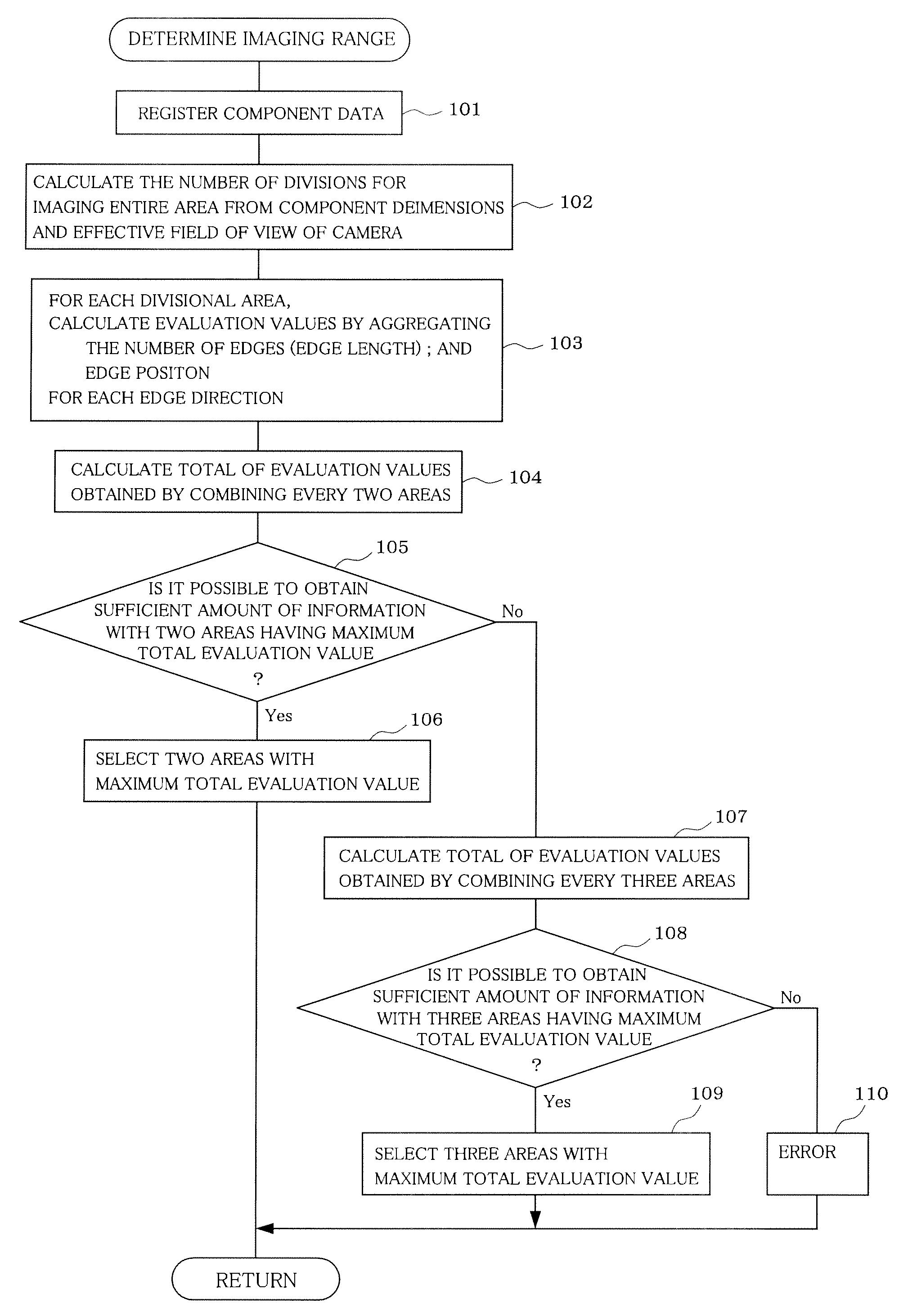
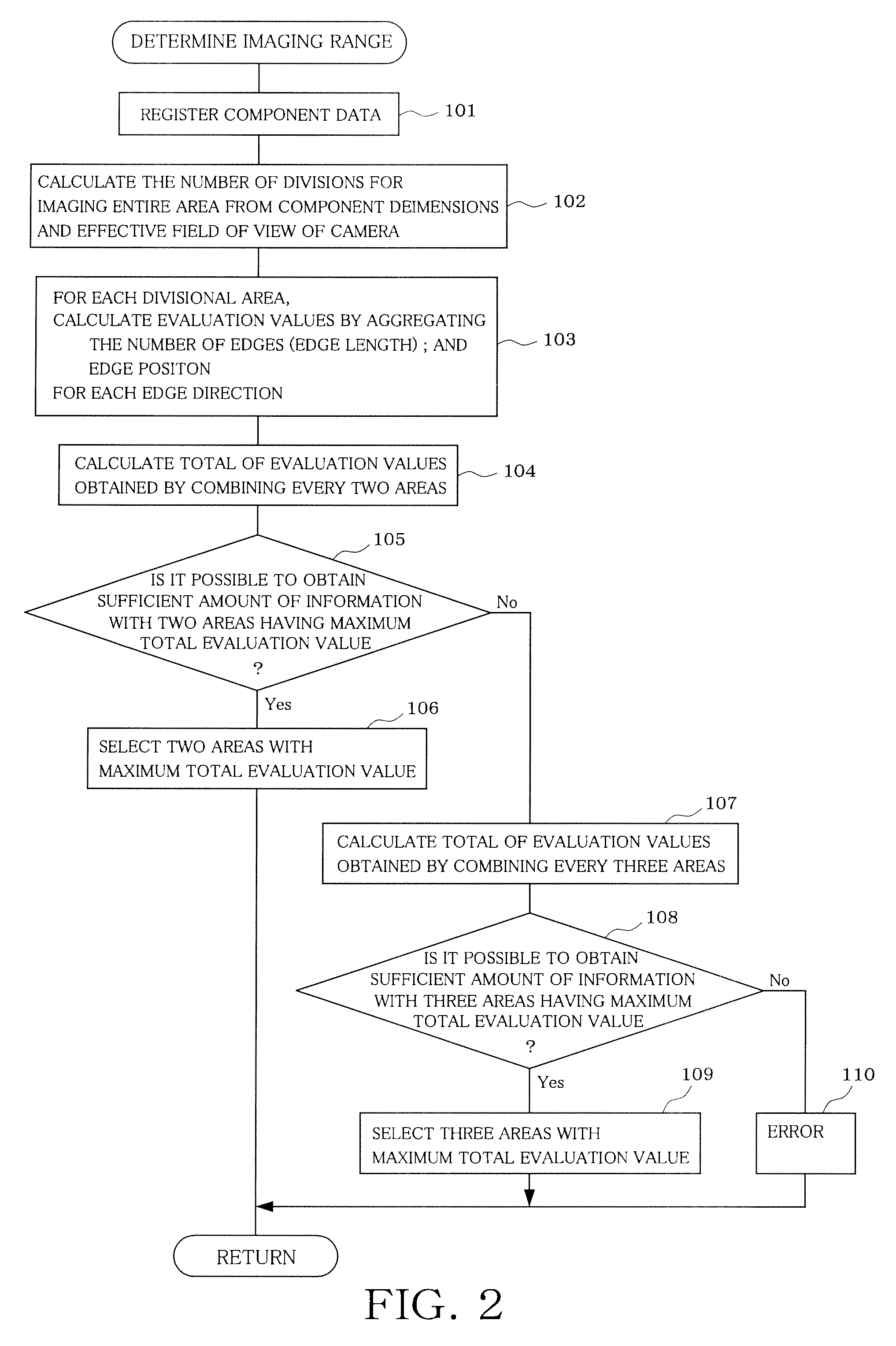
[0030]An embodiment in which a mode for carrying out the present invention is applied and implemented to a component mounting machine is described below.

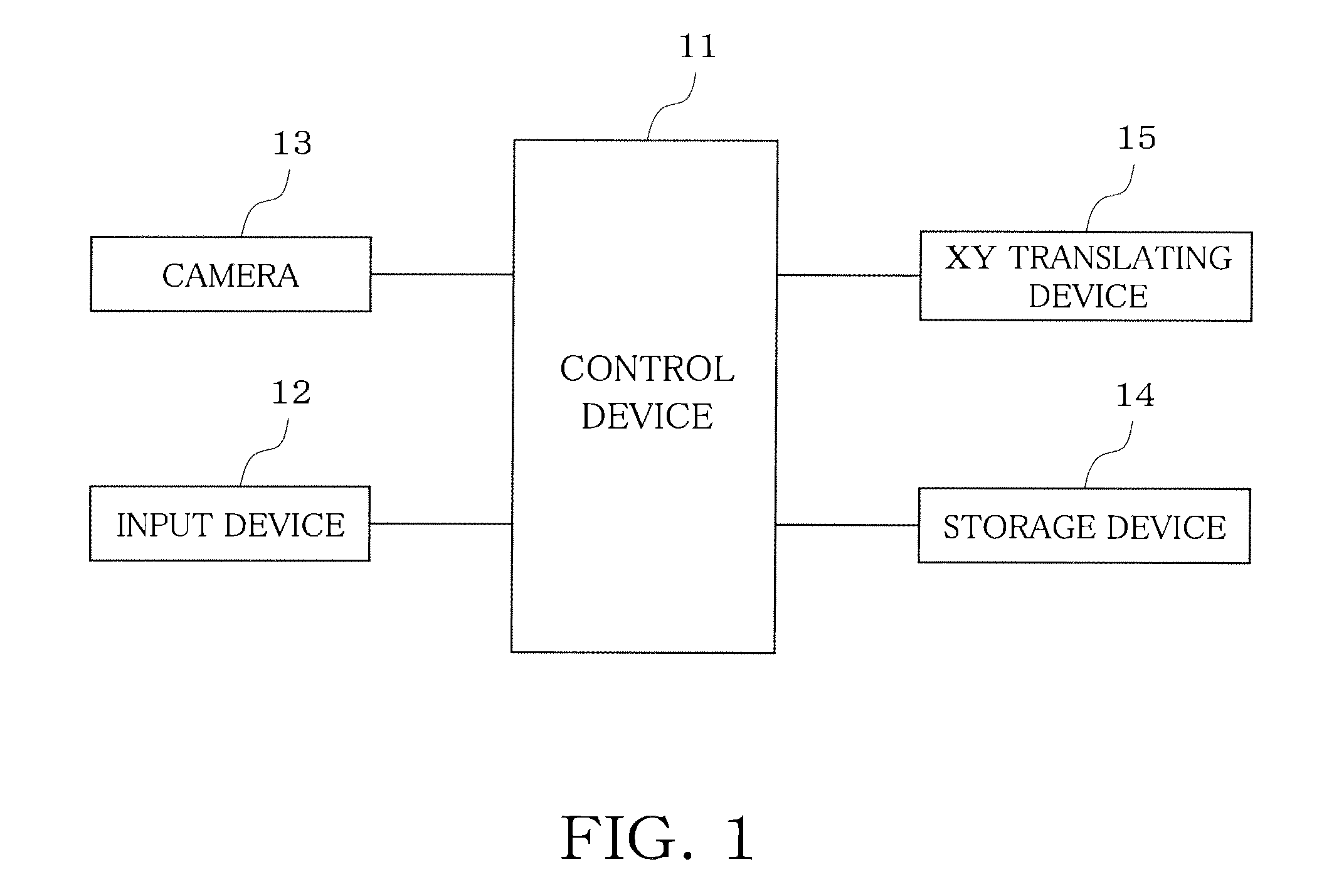
[0031]First, the structure of a component image processing apparatus is schematically described based on FIG. 1.

[0032]A control device 11 controls a component mounting machine and also controls component image processing, which will be described further below. For example, the control device 11 is configured of a computer, such as a personal computer or a work station. To this control device 11, an input device 12 such as a keyboard, a mouse, and a touch panel, a camera 13 imaging a component, and a storage device 14 such as a hard disk drive, an MO disk drive, and a USB memory storing various information such as various data and control programs.

[0033]When a component larger than the field of view of the camera 13 is to be imaged, the control device 11 causes a placing head (not shown) at which a suction nozzle suctioning a compone...


PUM


Abstract

To image a component larger than the field of view of a camera, a range based on the shape and dimension of the component to be imaged and the field of view of the camera, a range of the component is divided, and imaging ranges of a plurality of characteristic parts to be imaged are determined. Then, images of the plurality of characteristic parts obtained by imaging the plurality of characteristic parts with the camera are combined to create a combined image of the characteristic parts of the component. Based on the combined image, the position of the component is measured.

Description

BACKGROUND OF THE INVENTION[0001]1. Field of the Invention[0002]The present invention relates to a component image processing apparatus and component image processing method in which a component larger than the field of view of a camera is partially imaged for image processing and the position of the component is measured based on the image processing result.[0003]2. Description of the Related Art[0004]Conventionally, as depicted in FIG. 12, to image a component larger than the field of view of a camera for image processing, an entire area of the component to be imaged is divided into plural so as to come within the field of view of the camera, each divisional area is imaged by the camera, and then imaged images of the plurality of division areas are synthesized into a synthetic image of the whole component. Based on the synthetic image, a component position measuring process is performed (refer to Japanese Unexamined Patent Application Publication No. 2008-211009).[0005]This applic...

Claims


Application Information

Patent Timeline
Patent Type & Authority Patents(United States)
IPC IPC(8): G06K9/00G06T3/00G01B11/00G06T3/40
CPCG01B11/00G06T3/00G06T3/4038
Inventor OIKE, HIROSHISUGIYAMA, KENJI
Owner FUJI CORP
Why Eureka
Try Eureka