
Device and method for providing enhanced telephony

a technology of enhanced telephony and voice response, which is applied in the field of interactive voice response (ivr) systems, can solve the problems of frequent caller not being able to reach the desired end, time-consuming process, and caller frustration with ivr systems

Inactive Publication Date: 2014-11-04
LAVIAN TAL +1
View PDF4 Cites 22 Cited by
  • Summary
  • Abstract
  • Description
  • Claims
  • Application Information

AI Technical Summary

Benefits of technology

This invention provides a communication device with a database of visual Interactive Voice Response (IVR) menus associated with destinations. When the device dials a phone number of a destination, it compares it with phone numbers in the database and displays a form based on the comparison, containing data request fields for the visual IVR menu associated with the destination. This allows the caller to see the visual menu as they dial the phone number, without listening to the auditory menu. The visual IVR menu is also provided before connecting the device to the destination, enhancing the call experience.

Problems solved by technology

Therefore, the process can be time consuming.
As a result, a frequent caller may not be able to reach a desired end by remembering a combination of numbers.
Therefore, the caller may become frustrated with the IVR systems.
Therefore, the technique faces various practical limitations.
IVR menus can be time consuming.
However, this may be time consuming for the customer.
Moreover, the customer may be not being able to talk to another executive during the call in case the on-line executive is not able to satisfy the customer.
However, the customer is still required to request the webpage with embedded information from a server of the organization.
Moreover, the methods and systems are limited to the organizations that provide the required webpage to the customers.
However, the technique discussed in the paper is limited to the visual content provided by the service provider's end, after the connection is established.
As discussed above the existing technologies have various limitations.

Method used


Image

  • Device and method for providing enhanced telephony
  • Device and method for providing enhanced telephony
  • Device and method for providing enhanced telephony

Examples


Embodiment Construction

[0046]Illustrative embodiments of the invention now will be described more fully hereinafter with reference to the accompanying drawings, in which some, but not all embodiments of the invention are shown. Indeed, the invention may be embodied in many different forms and should not be construed as limited to the embodiments set forth herein; rather, these embodiments are provided so that this disclosure will satisfy applicable legal requirements. Like numbers refer to like elements throughout.

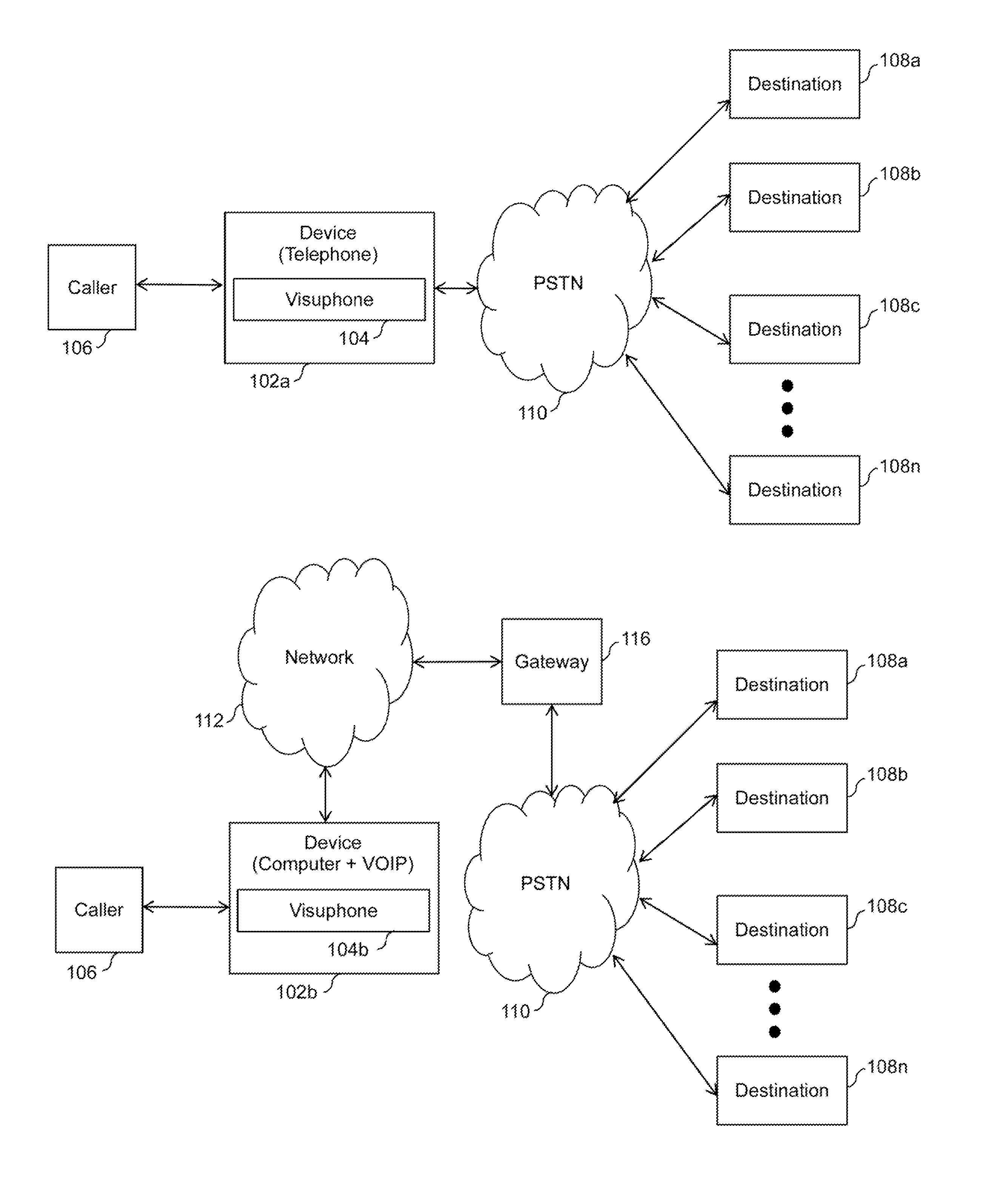
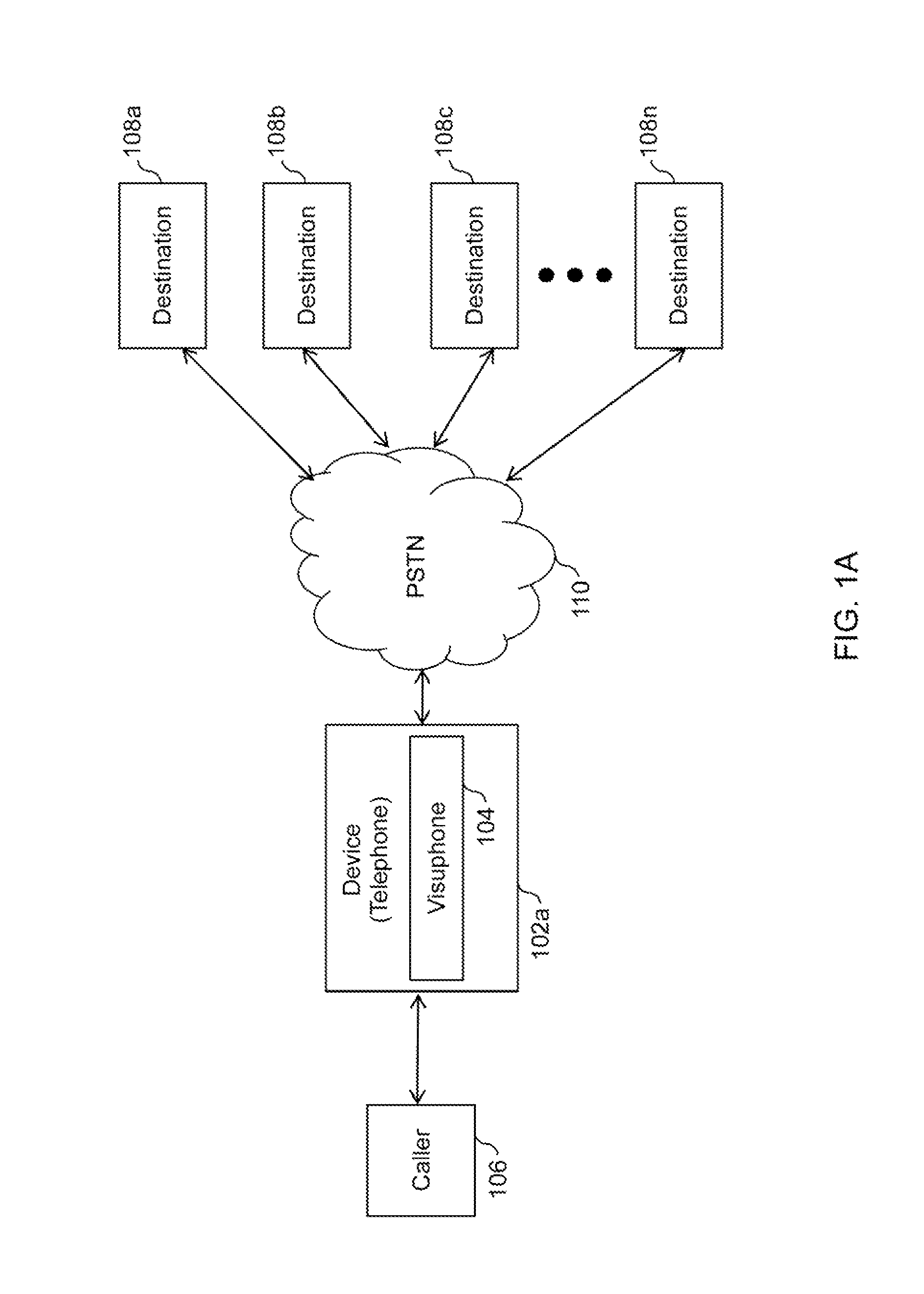
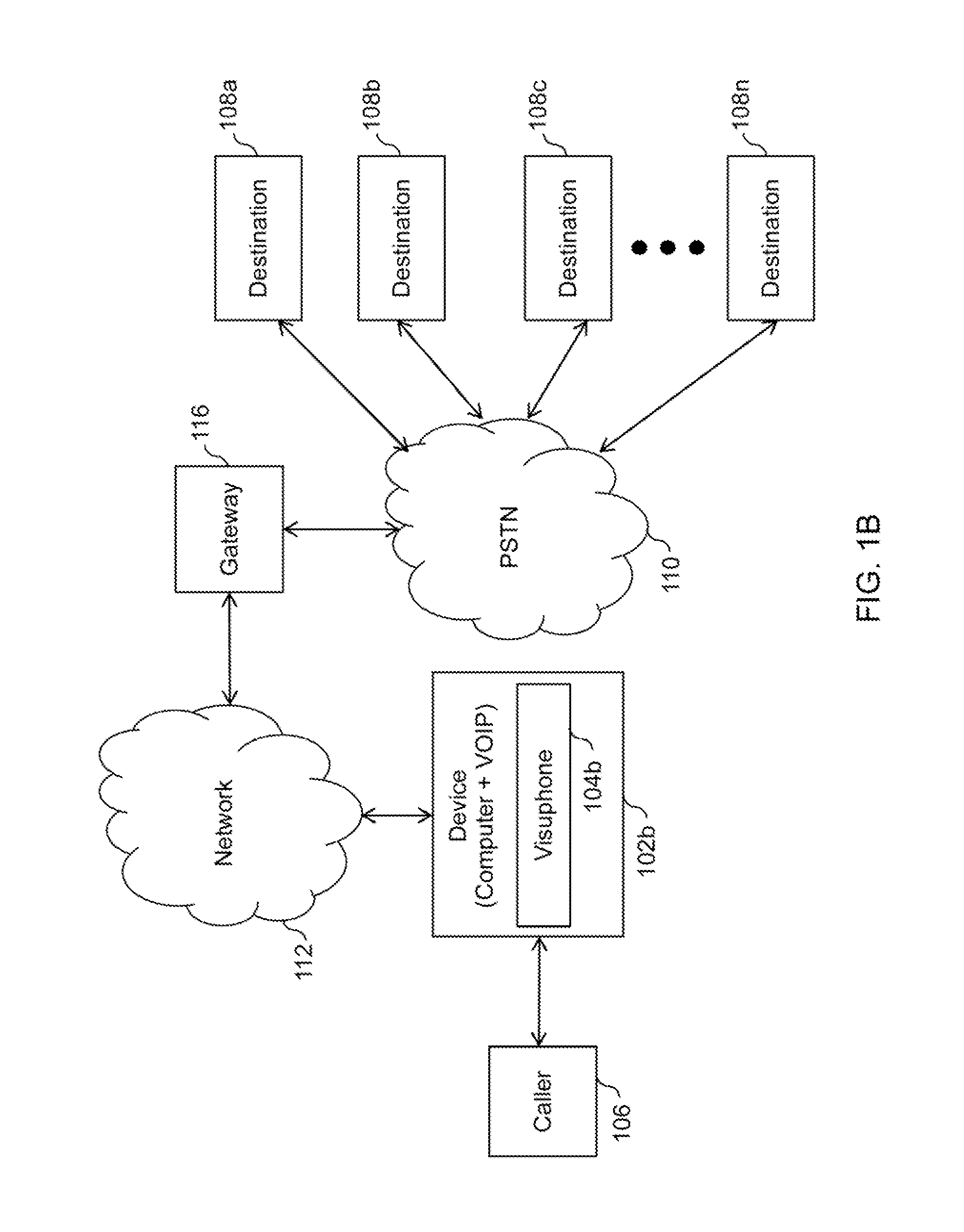
[0047]FIG. 1A illustrates an exemplary environment where various embodiments of the invention function. A caller 106 may use a device 102a to connect to destinations 108a-n. Device 102a can be a telecommunication device that can connect directly to a Public Switched Telephone Network (PSTN) 110. A person skilled in the art will appreciate, that device 102a can also connect to a private telephone exchange. Examples of device 102a include, but not limited to, a telephone, a mobile phone, a Smartph...


PUM


Abstract

Embodiments of the invention provide a communication system including a processor and a memory coupled to the processor. The memory includes instructions executable by processor to communicate with a database comprising a plurality of visual integrated voice response (IVR) menus associated with a plurality of destinations. Further, the instructions executable by the processor for receiving a dialed phone number of a destination. Furthermore, the instructions executable by the processor for comparing the dialed phone number with phone numbers stored in the database. Additionally, the instructions executable by the processor for transferring to be displayed a form based on the comparison. Herein, the form comprises one or more data request fields corresponding to a visual IVR menu associated with the dialed destination.

Description

CROSS REFERENCE TO RELATED APPLICATIONS[0001]This application is a Continuation of U.S. Non-Provisional application Ser. No. 13 / 022,909 entitled ‘Device and Method for providing enhanced telephony’ and filed on Feb. 8, 2011, which is Continuation-In-Part (CIP) of U.S. Non-Provisional application Ser. No. 12 / 699,618 entitled ‘Systems and methods for visual presentation and selection of IVR menu’ and filed on Feb. 3, 2010.FIELD OF THE INVENTION[0002]The invention relates to Interactive Voice Response (IVR) system and more specifically the invention relates to presentation and visual selection of IVR option from a caller device.BACKGROUND OF THE INVENTION[0003]Interactive Voice Response (IVR) technology is generally used to detect voice and key inputs from a caller. Various organizations such as banks, insurance companies, and other service providers use IVR technology to manage calls from their customers. Typically, IVR systems are used by organizations that have high call volumes. An...

Claims


Application Information

Patent Timeline
Patent Type & Authority Patents(United States)
IPC IPC(8): H04M3/493H04M1/00
CPCH04M3/493H04M2203/254H04M2203/252H04M2201/42
Inventor LAVIAN, TALOR-BACH, ZVI
Owner LAVIAN TAL
Learn More